4. Core & Sensor Tank
This instruction shows how to swap the Core and Sensor Tank in a Hatch LK or Hatch Cabinet installation, where the Core is installed outside of the shower area, inside the Wall Box. Follow the instructions in detail, and don't hesitate to reach out if you have any questions - support@orbital-systems.com.
Use the kits below to swap the Core and Sensor Tank.
Core |
Filter Capsule |
or
Core Refurbished |
Filter Capsule |
Sensor Tank |
Sensor cable |
Flush hose |
Recirculation hose |
Tank accessory parts |
Dismantle Core
Turn off the power.

Turn off the incoming hot and cold water.
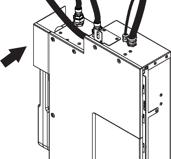
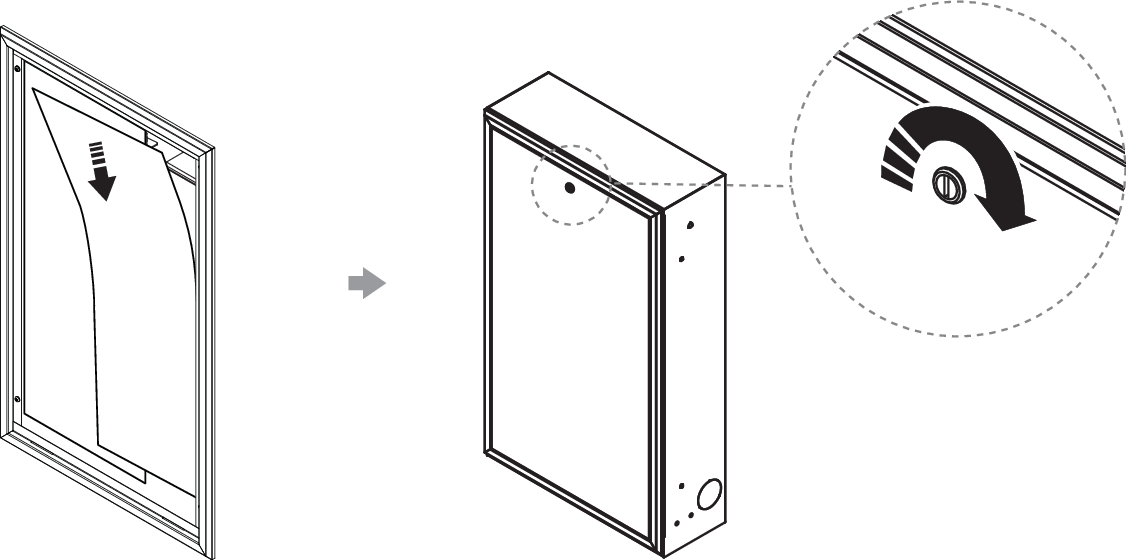
Open the door to the Wall Box and put the door and splash guards aside.
Open the door on the Core and release the Filter hatch.
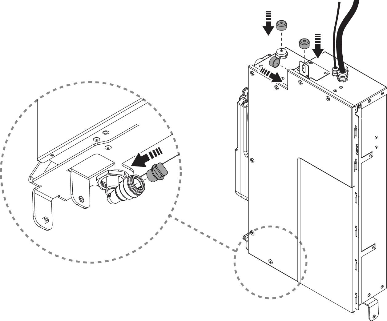
Remove the Filter Capsule. Use the plugs from the Filter hatch in the new Core and transfer to the old one. The larger plug should be placed in the upper bracket, and the smaller plug in the lower one.
Close the hatch and the door.
Remove the air gap tank cover and set it aside.
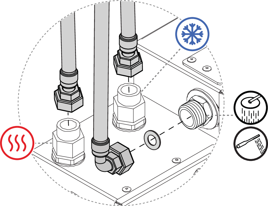
Disconnect the shower water connection (outgoing). Then, disconnect the water connections for incoming hot and cold water. Wipe off any remaining water that drains from the pipes.
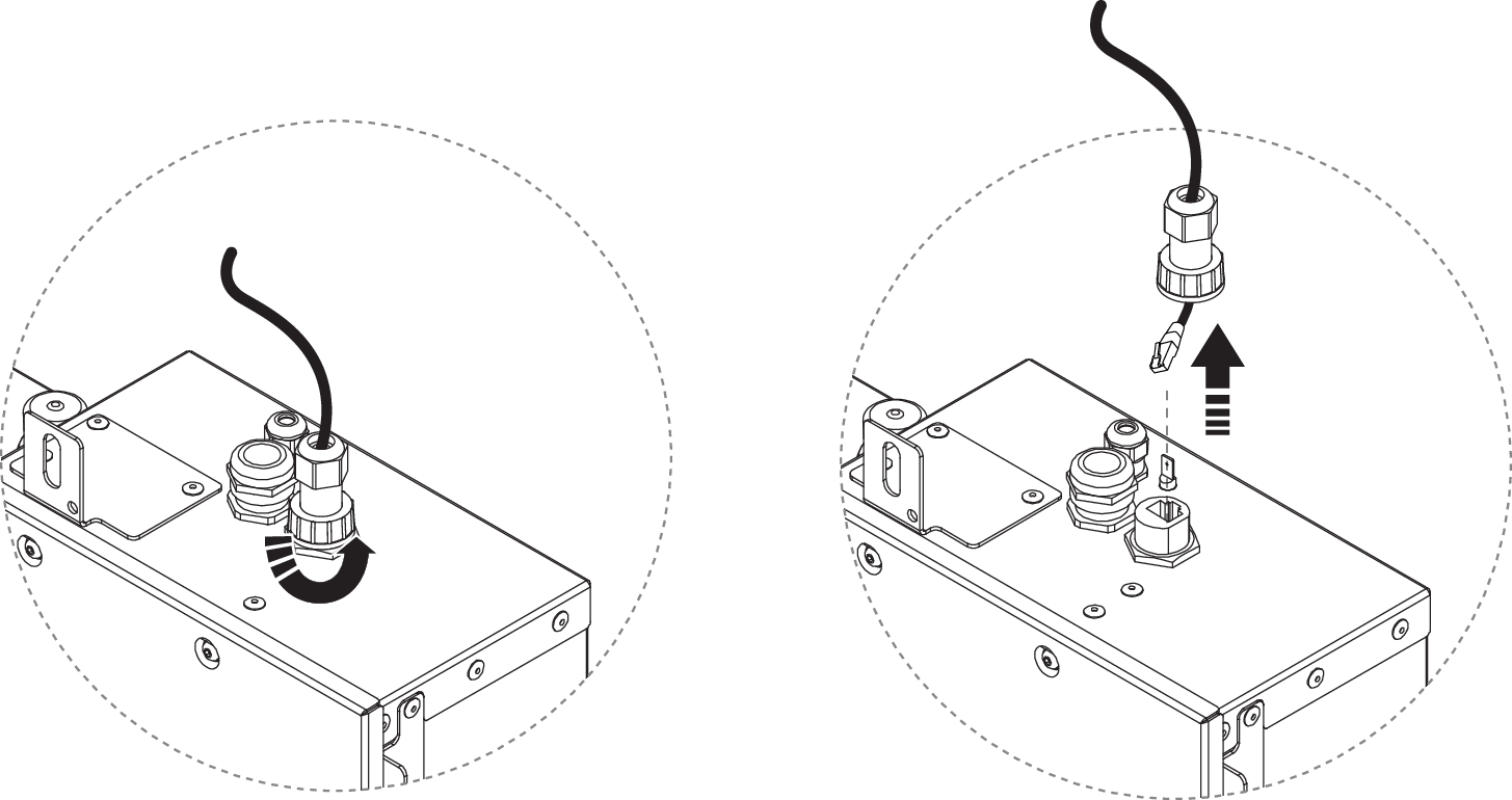
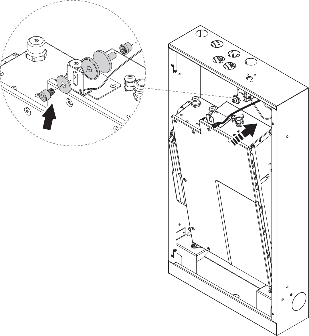
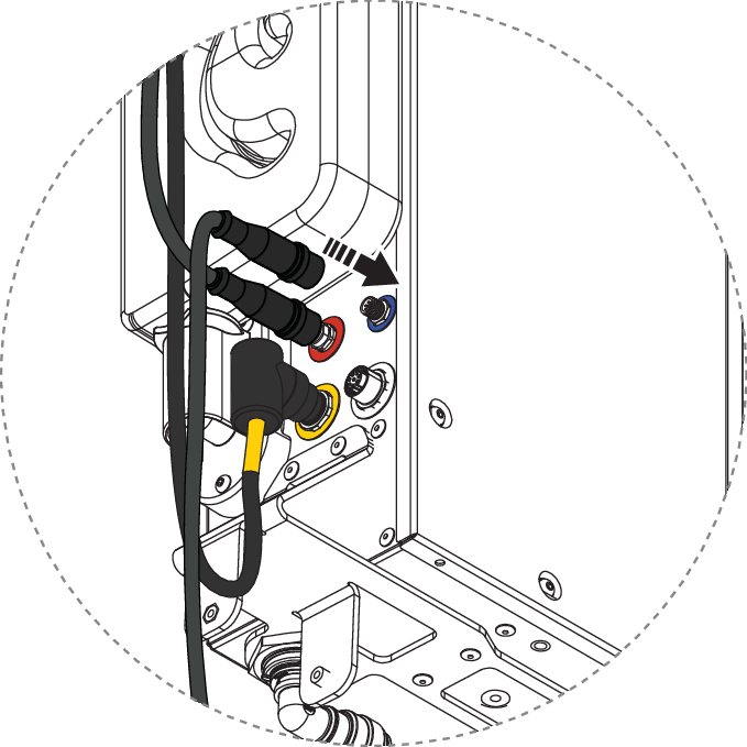
Disconnect the Wi-Fi antenna cable.
For Ethernet installation: Unscrew the protective cover and disconnect the Ethernet cable.
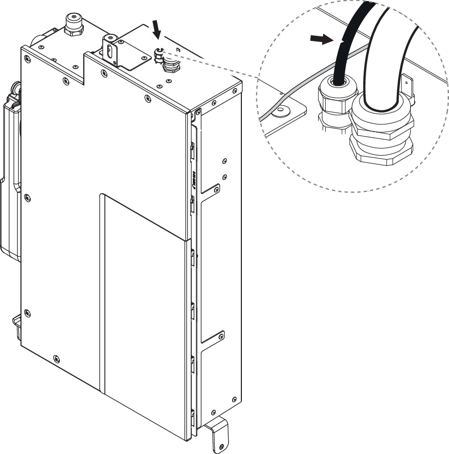
Disconnect the flush hose and recirculation hose from the bottom of the Core.

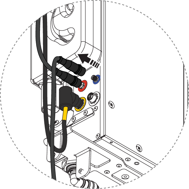
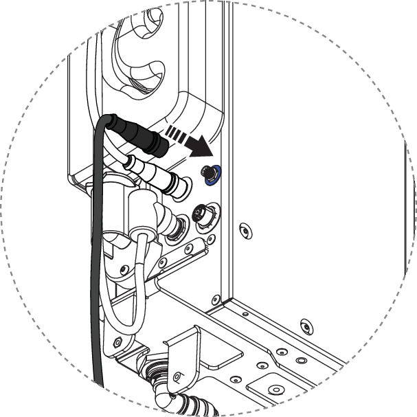
Disconnect the Sensor Tank and Control Dial (red and blue connector). For installations with Orbital Audio, do also disconnect the amplifier (yellow connector).
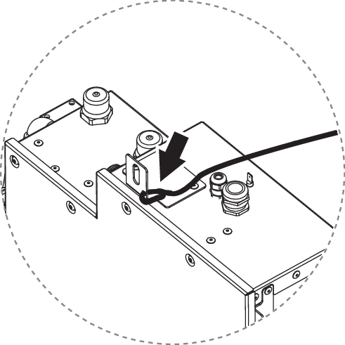
Make sure the safety wire is connected to the Core and Wall Box.
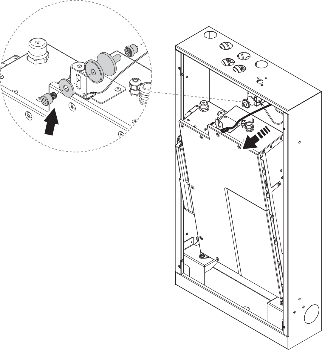
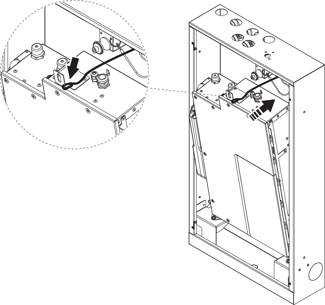
Unscrew the Core from the top vibration damper and gently lean it forward until the wire is fully extended and holds the Core.
Make sure the power is off. Then unscrew the lid of the electrical box and set it aside.
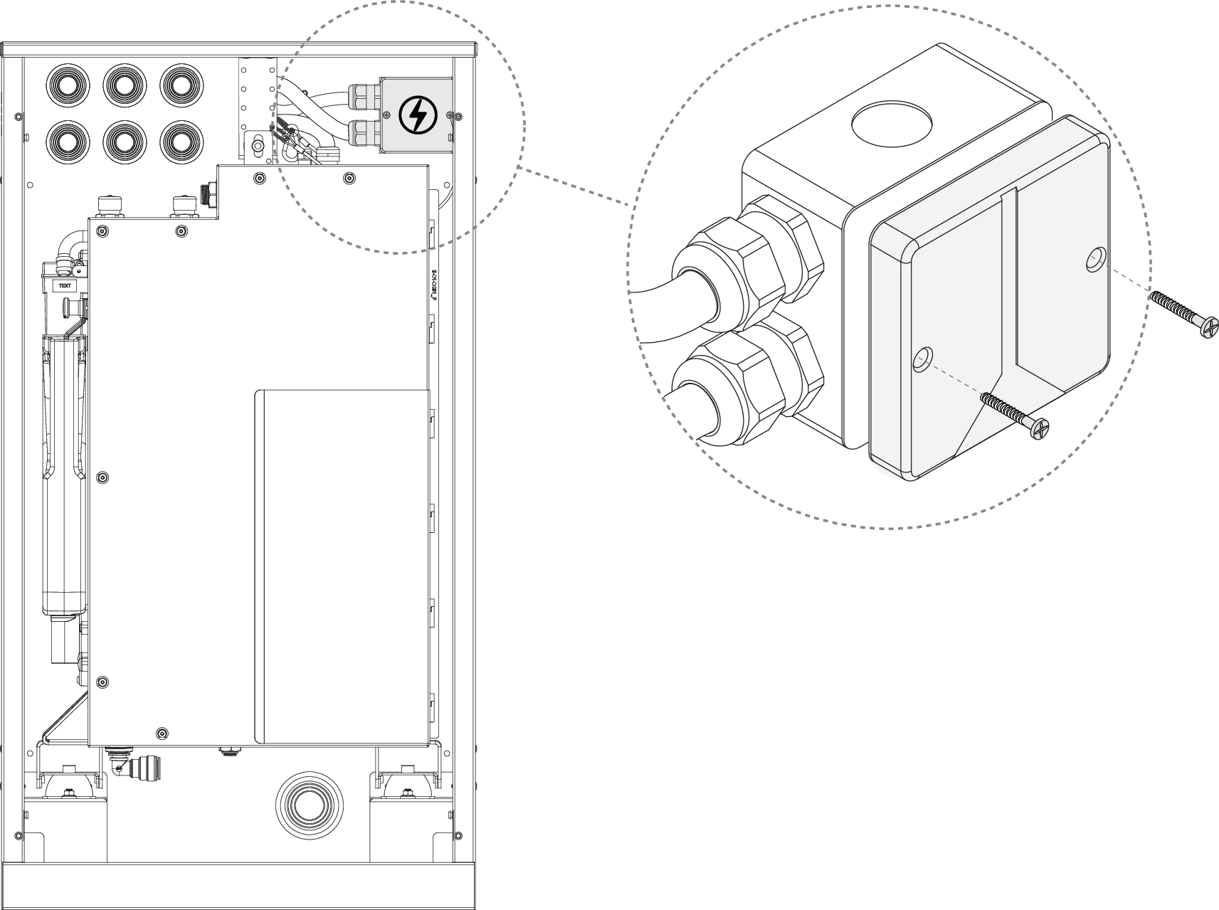
Loosen the strain relief. Disconnect the cables and pull out the power cable to the Core from the electrical box.
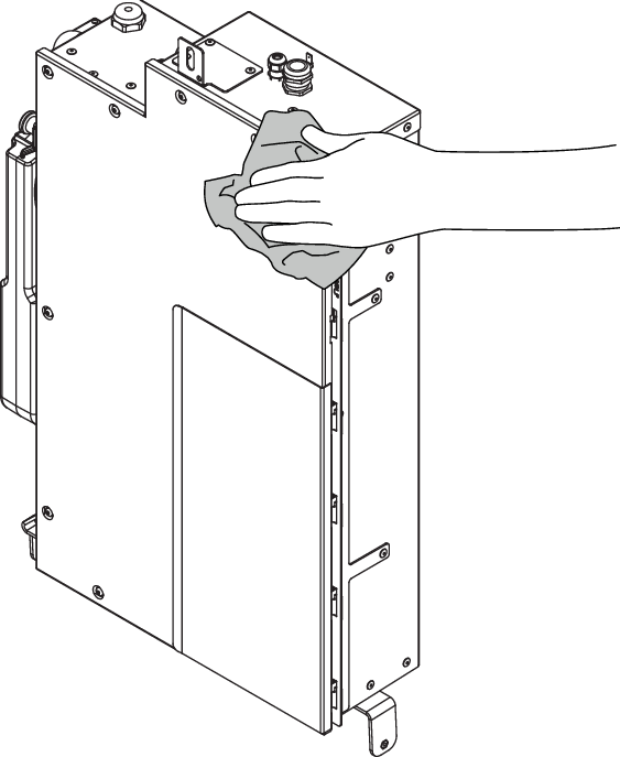
Wipe off the Core thoroughly. This is important to ensure a proper grip when lifting it out.
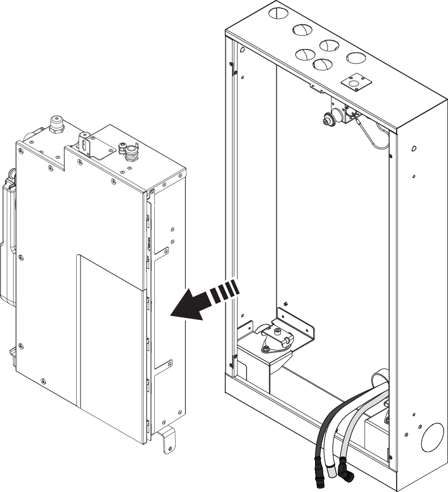
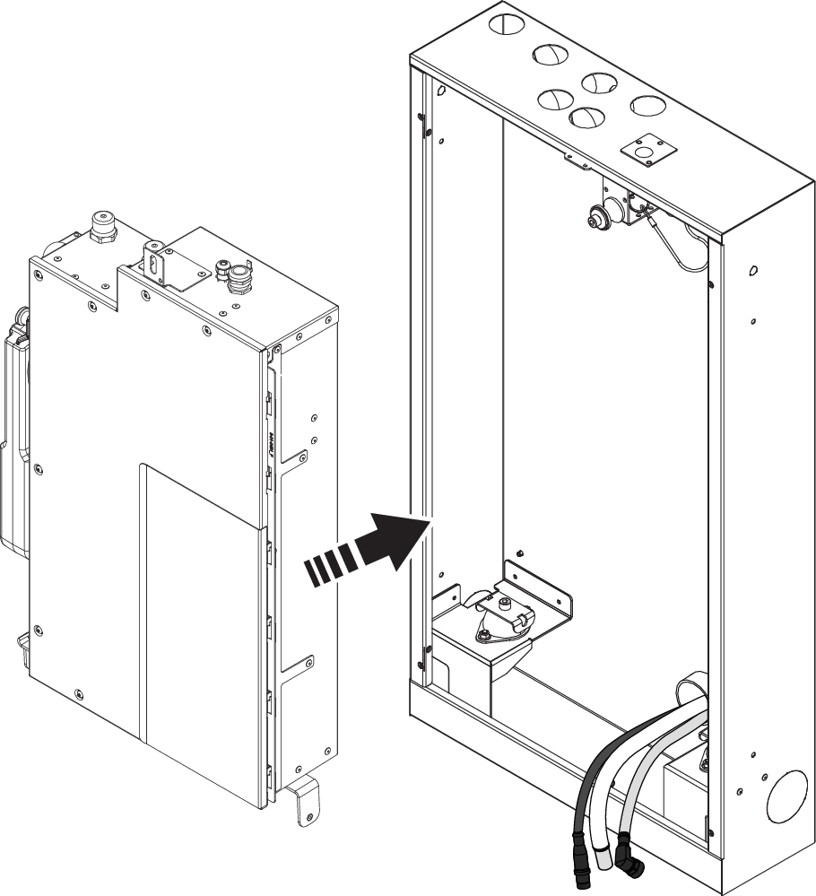
Disconnect the safety wire and lift out the Core. Put it in a safe and stable place.
Dismantle Sensor Tank
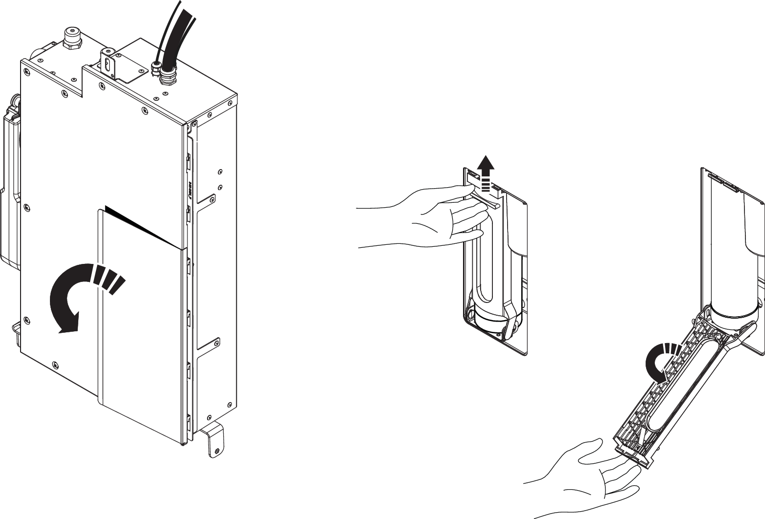
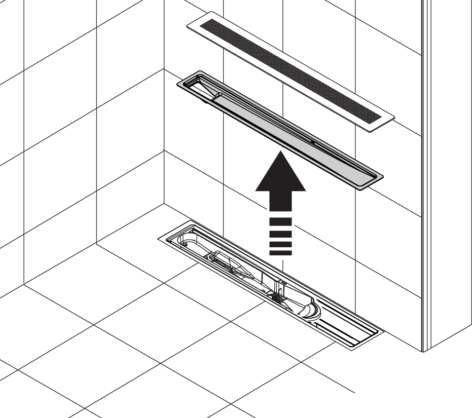
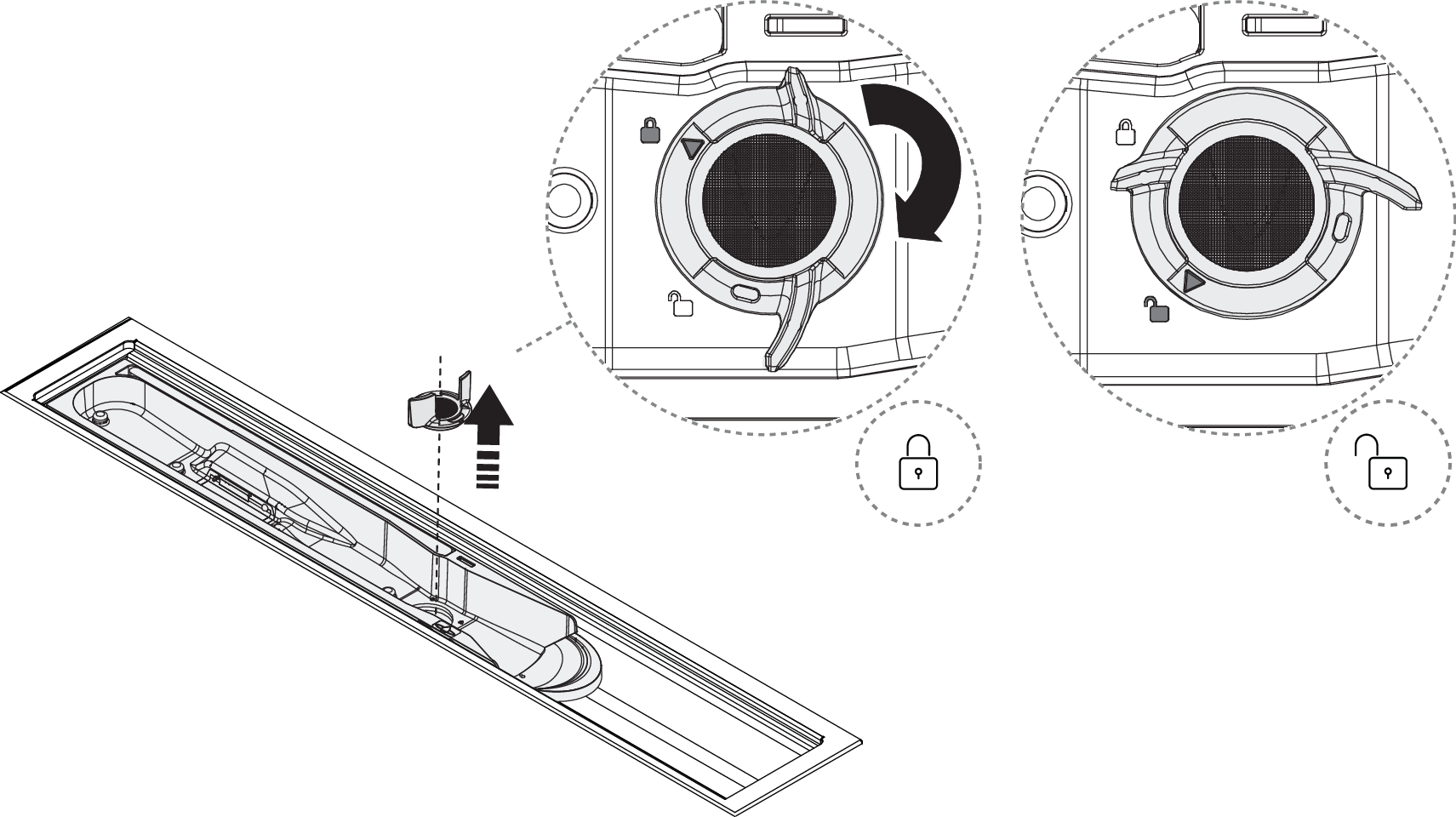
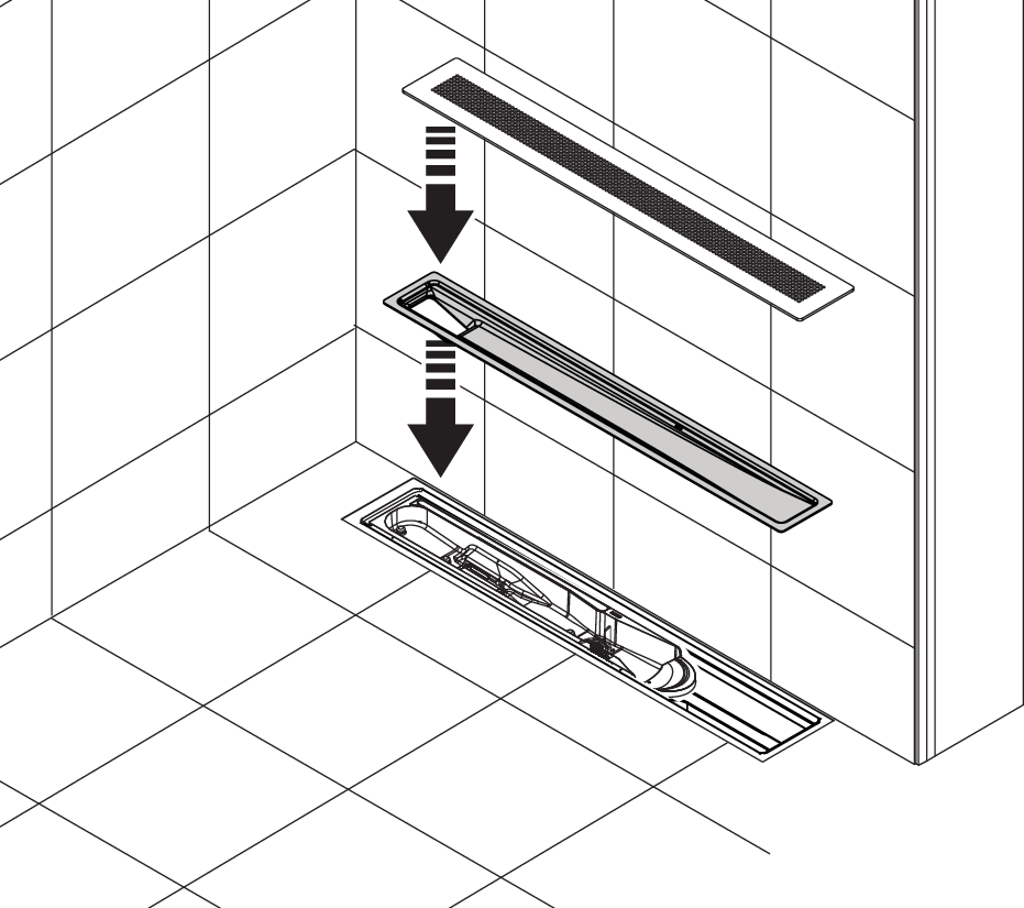
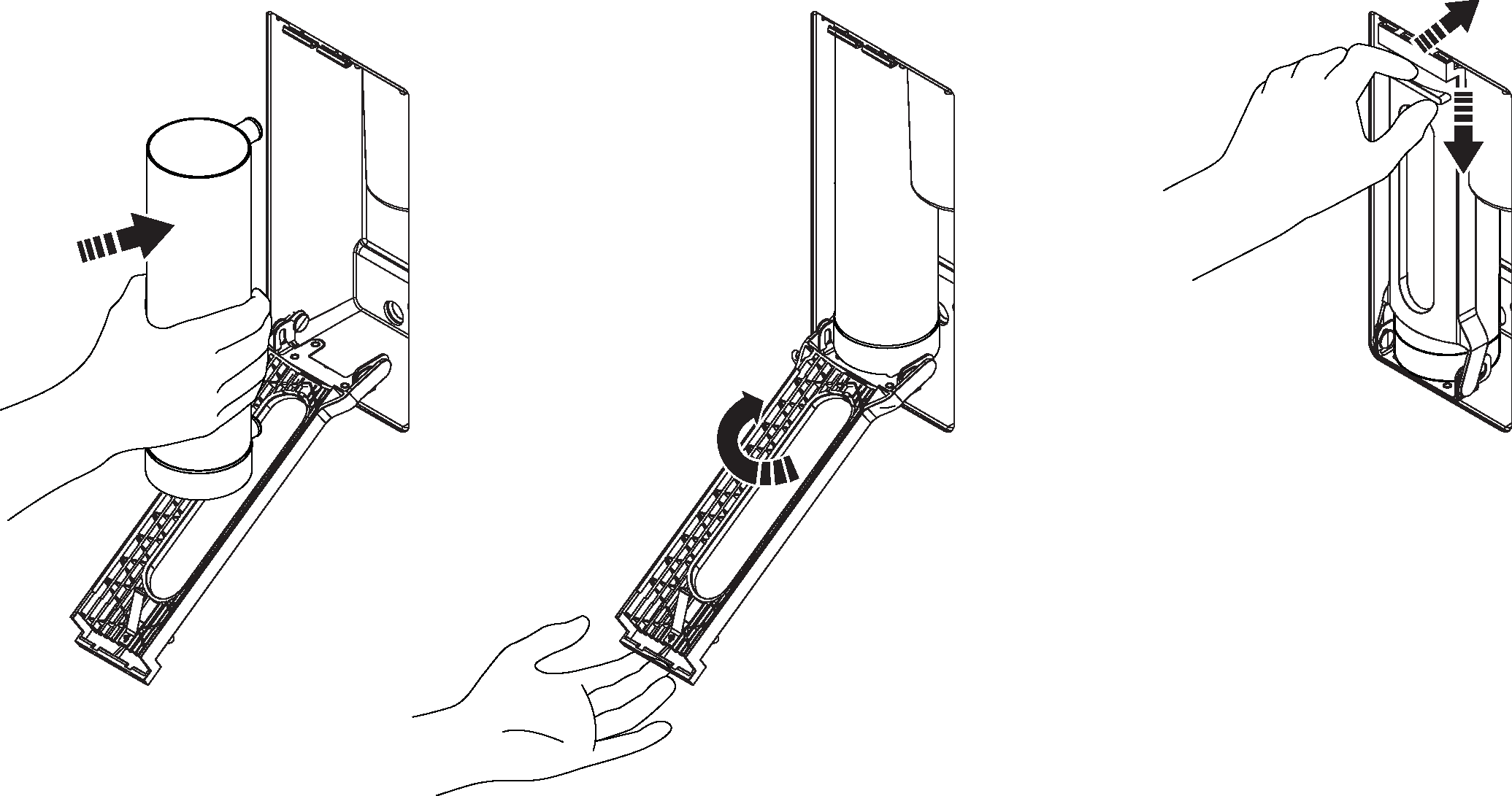
Lift the grate and Funnel.
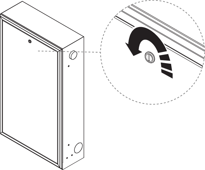
Unlock the Sensor Tank by turning the Sensor Tank Lock 90° counterclockwise.
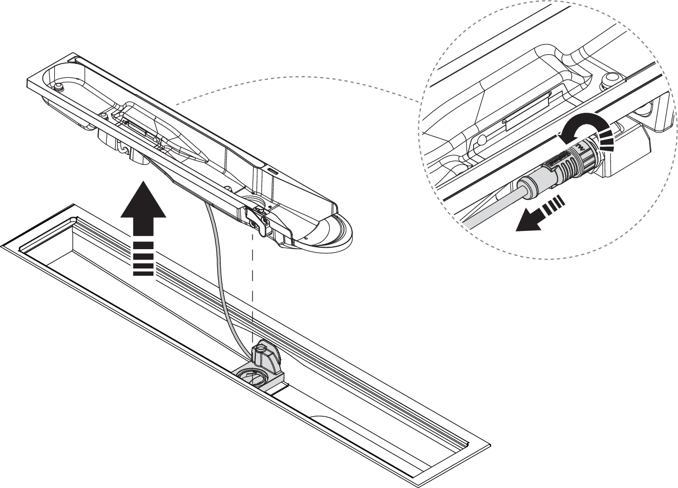
Lift the Sensor Tank and disconnect the sensor cable by unlocking the connector. Turn the connector flange 90° counterclockwise to unlock.
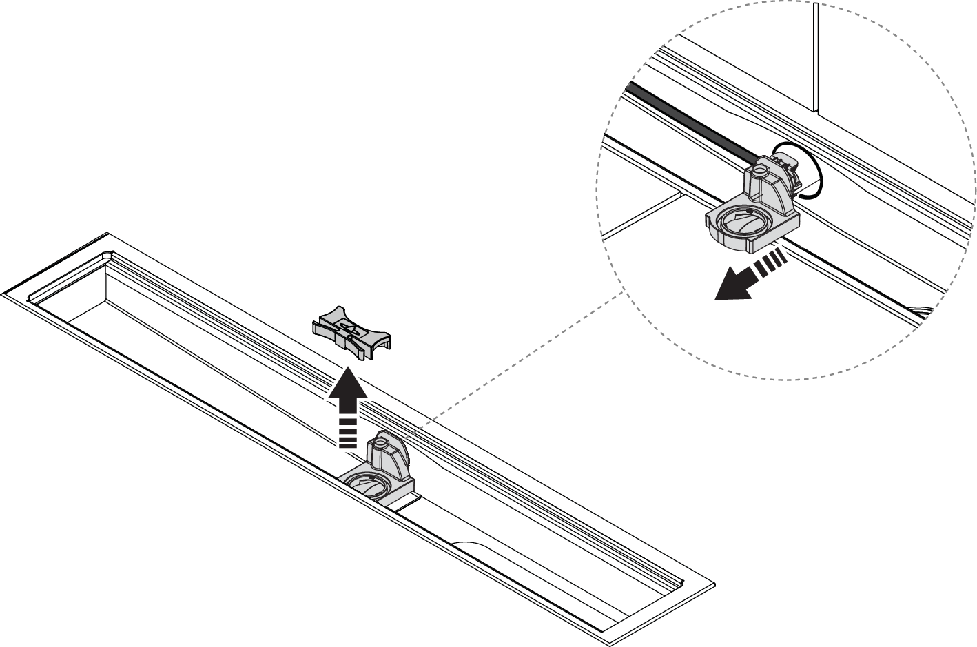
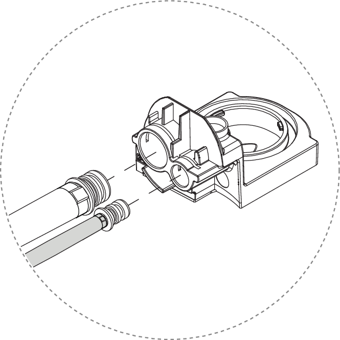
Remove the spring lock and pull out the Sensor Tank dock.
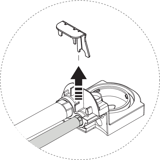
Remove the clip to release the hoses.
Release the Sensor Tank dock.
Pull out the flush hose.
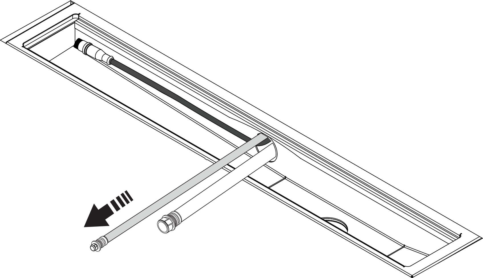
Pull out the recirculation hose.
Caution
It is important that the circulation hose is pulled out from the top, to minimize the risk of the hose coupling getting stuck in the pipe.
Note that the location of the Core varies depending on the customer's model. The connection pipe can be located on the right or left side of the Wall Box or in the back.
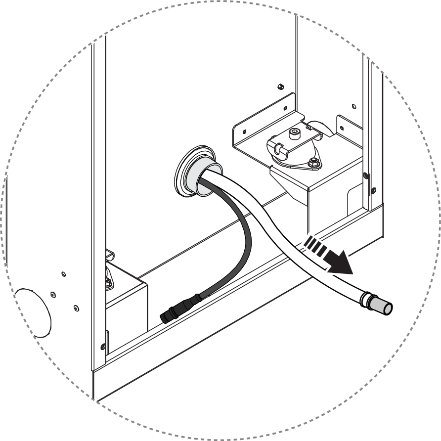
Pull out the sensor cable.
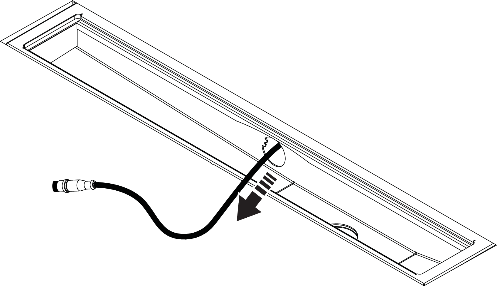
Install Sensor Tank
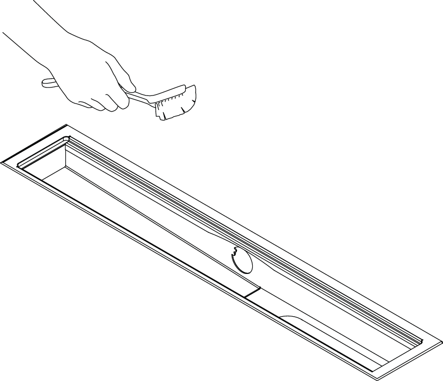
Clean the drain unit.
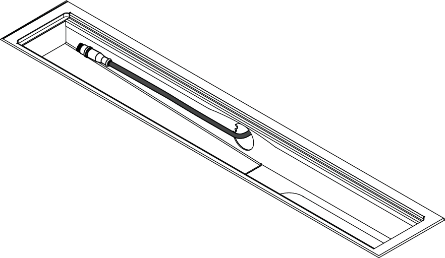
Route the sensor cable from the Wall Box through the connection pipe with the large connector down to the Sensor Tank. Pull out the cable to where it is about 150 mm left in the drain unit.
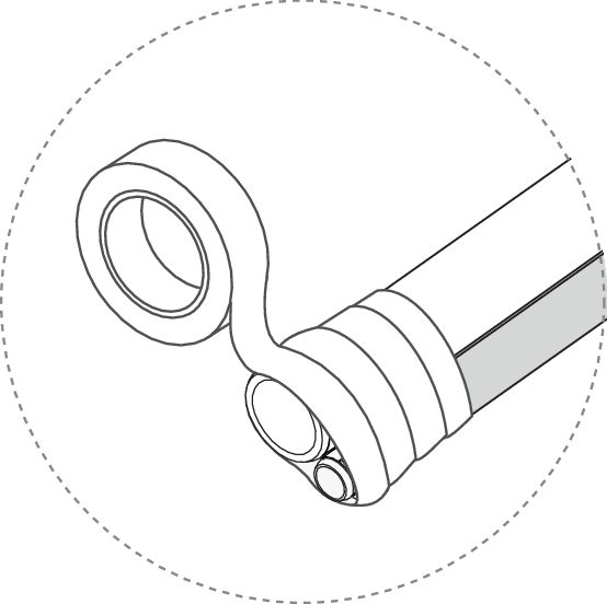
Tape the flush hose and the recirculation hose together at the end of the couplings, flush hose on the left. Make sure that the couplings, especially the o-rings, are carefully covered with tape.
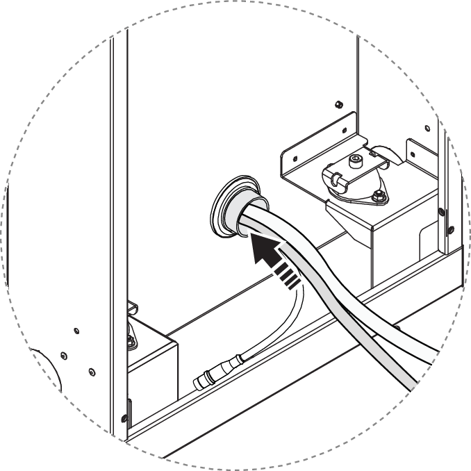
Pull the hoses through the connection pipe, with the couplings down towards the Sensor Tank. A tension spring is recommended for smooth installation.
Apply fitting grease and connect the hoses to the Sensor Tank dock.
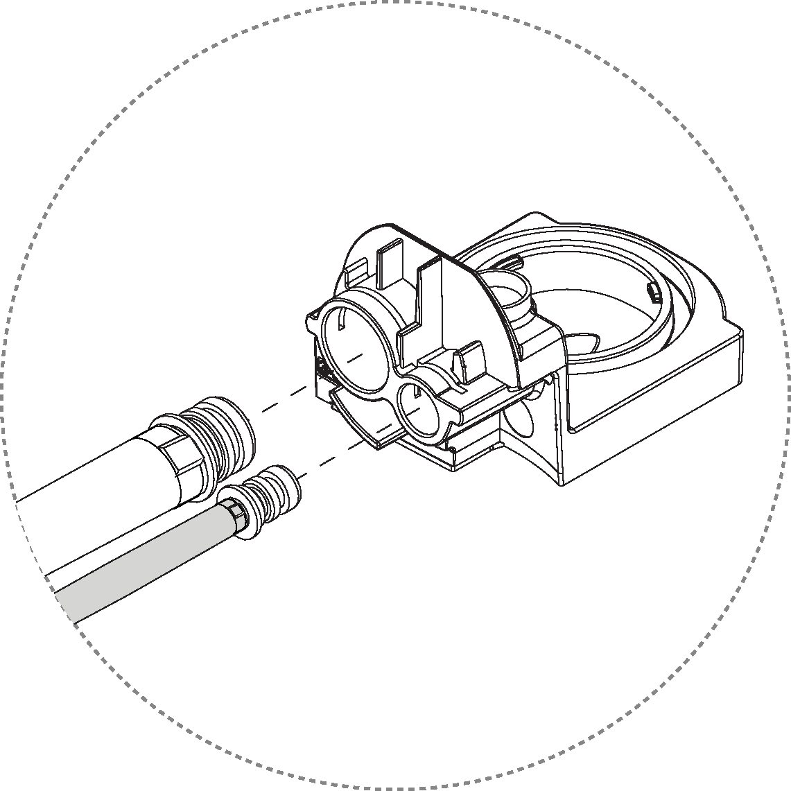
Lock the hoses using the clip. Press the clip down until it clicks.
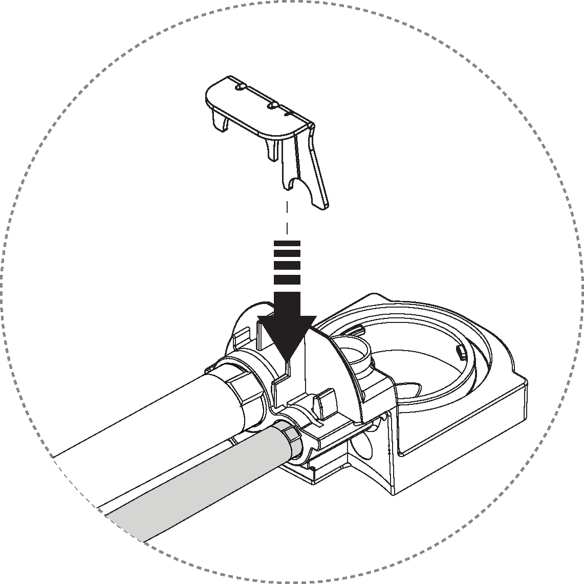
Insert the dock into the connecting pipe and push it all the way in.
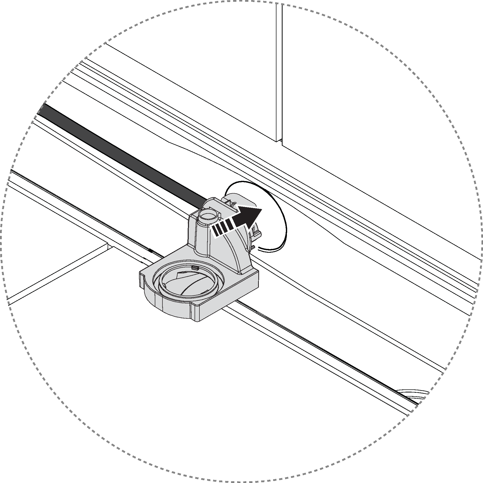
Lock the Sensor Tank dock in place with the spring lock. Ensure that the sensor cable is not pinched.
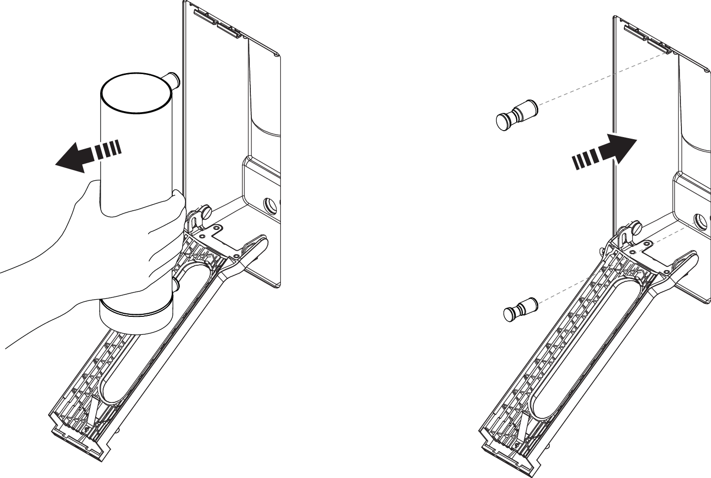
Apply grease to the Sensor Tank o-rings.
Remove the protective cap from the sensor cable, and connect the cable to the Sensor Tank.
Caution
Make sure to have correct alignment between the groove and the pin when connecting.
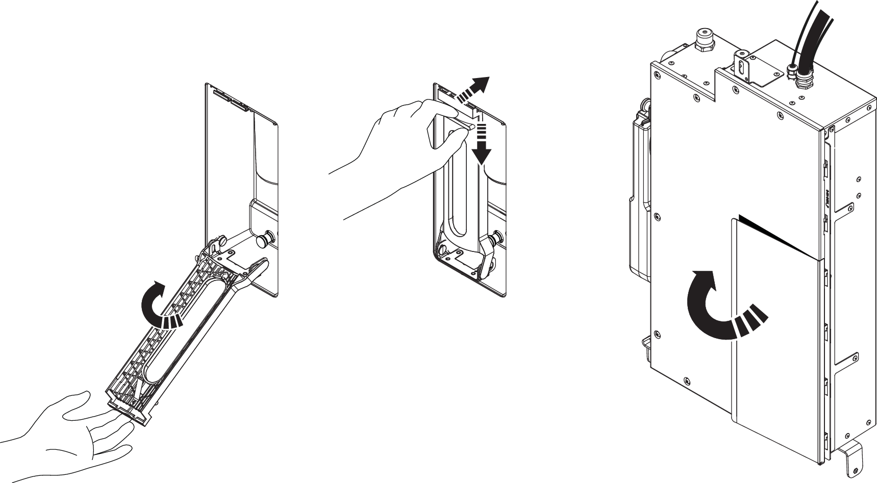
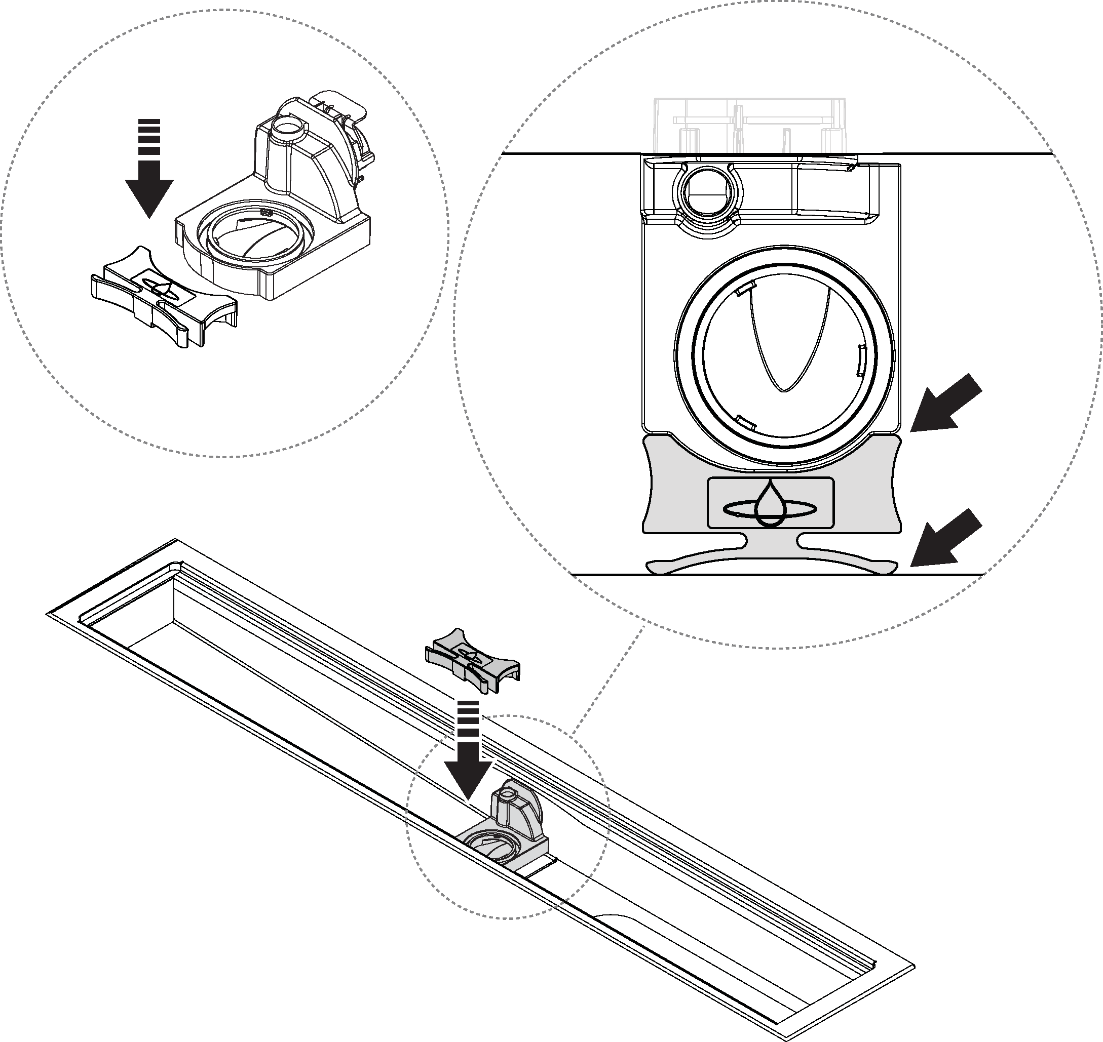
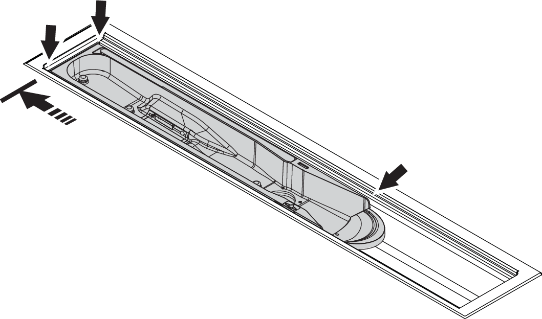
Insert the Sensor Tank to the drain unit.
Caution
Make sure the Sensor Tank is inserted correctly. Its edge should be fully pushed towards and at level with the edge of the drain unit.
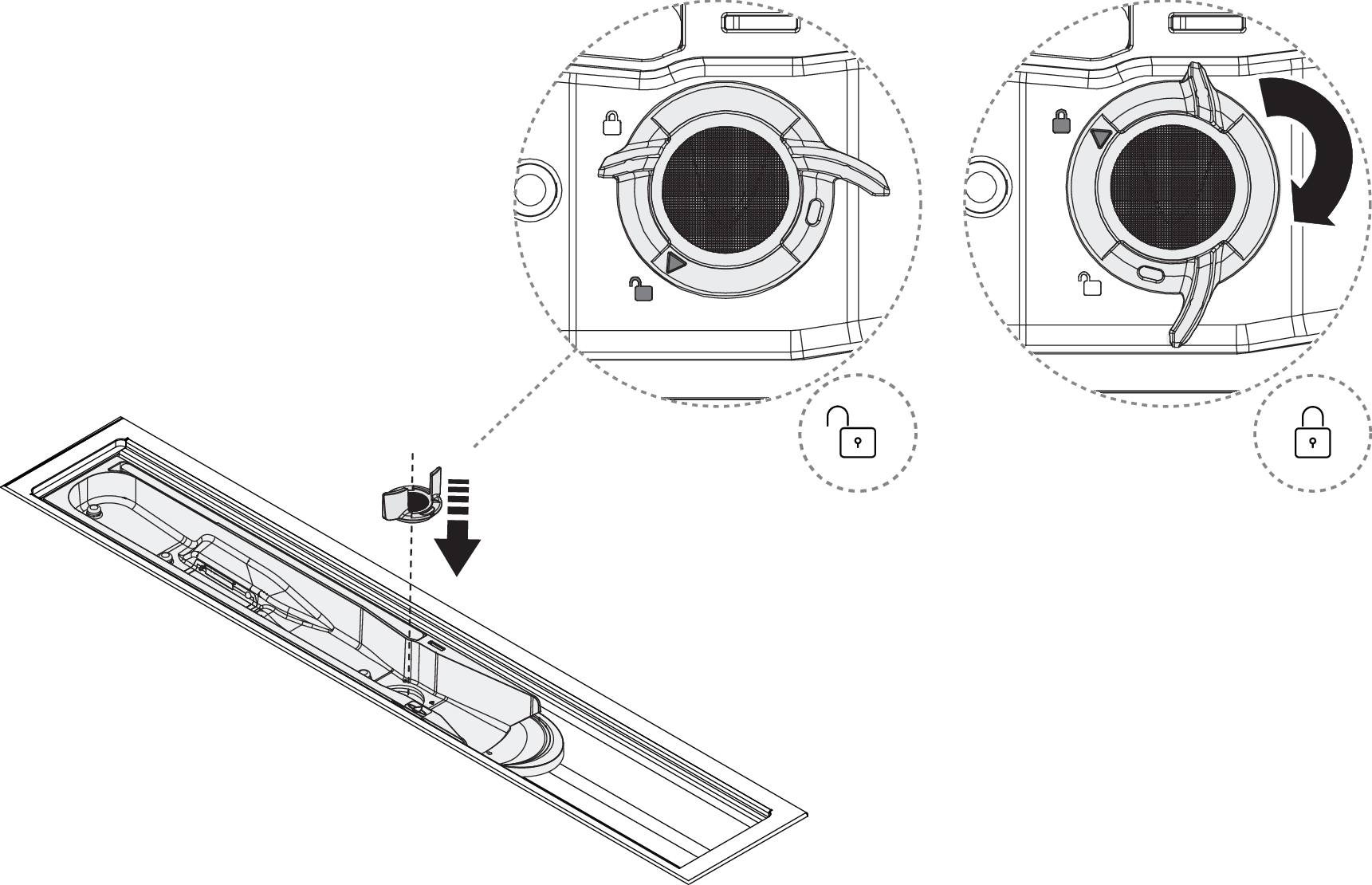
Lock the Sensor Tank in place by turning the Sensor Tank Lock 90° clockwise.
Place the Funnel and grate back in place.
Note
Place the Funnel with the hole oriented to the left! Placing the hole oriented to the right will disable recirculation.
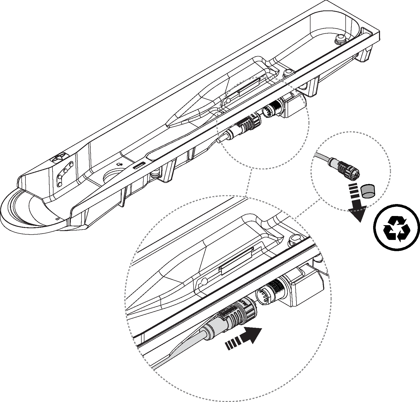
Connect the sensor cable to the communication port on the Core (blue port). The connector should be tightened by hand.
Caution
Ensure correct alignment between the connector and communication port. This must be done with particular attention to prevent damage to the pins.
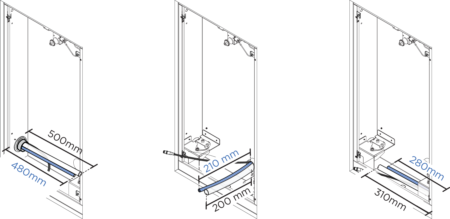
Cut the circulation hose and the flushing hose according to the measurements below from the rubber grommet of the Wall Box, or from the connection pipe in the case of an installation with Basic, depending on the installation.
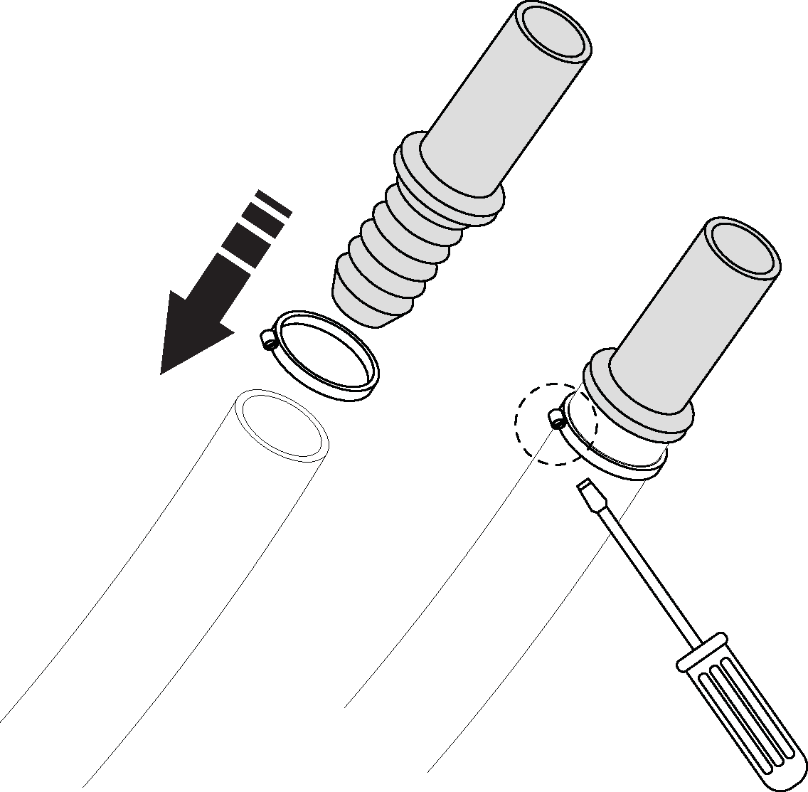
Apply fitting grease to the separate hose coupling, push all the way into the circulation hose and tighten with the hose clamp.
Install Core
Take the new Core out of the packaging and put it in a safe and stable place. Make sure that the packaging and pallet are saved in good condition - they should be reused when returning the replaced Core. Also, save the foam inserts to ensure that the Core can be sent back in a safe and stable way.
Transfer the transport plugs from the new Core to the old one.
Place the new device in the Wall Box. The Core should click all the way into the vibration damper.
Attach the safety wire to the Core and keep it in the tilted position.
Feed the stripped part of the electrical cable into the electrical box and tighten the strain relief.
Connect the cables and screw the lid back to the electrical box.
Lean back and screw the Core onto the vibration damper. Make sure the electrical cable is placed behind the hot water pipe without any sharp bends, and make sure it is not pinched behind the Core.
Open the Filter hatch and insert a Filter Capsule.
Connect the hot and cold water connections. Then connect the shower water connection to the Core.
Caution
Make sure the gaskets are in good condition and have no damage.
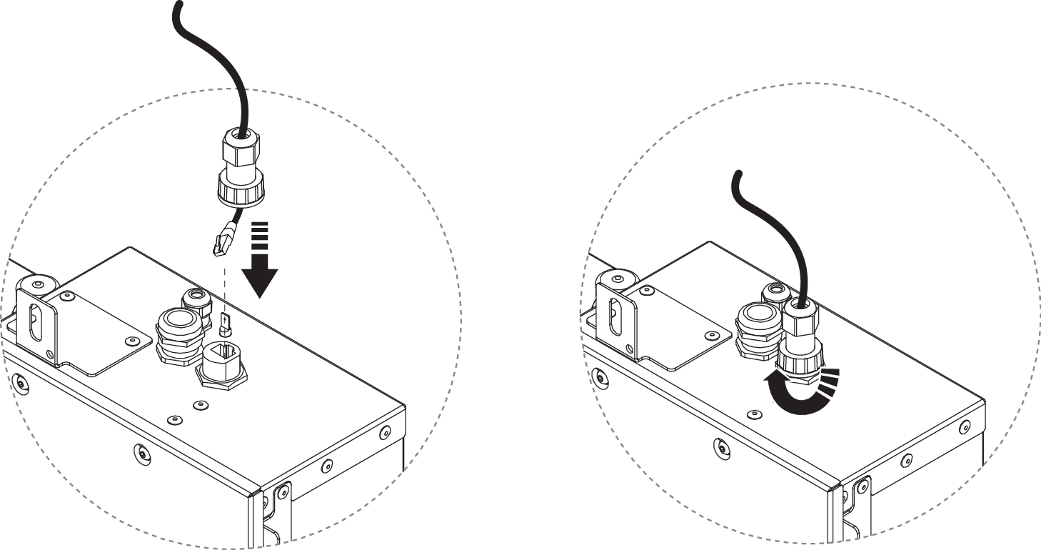
Connect the Wi-Fi antenna cable.
For Ethernet installation: Unscrew the protective cover and connect the Ethernet cable.
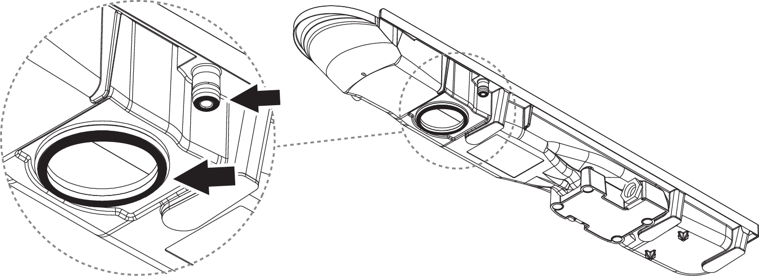
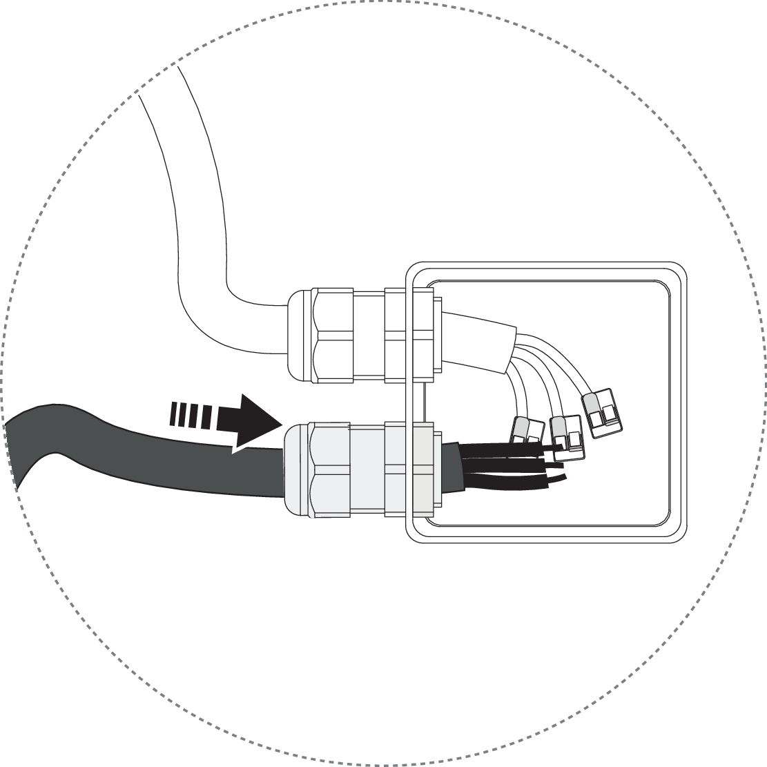
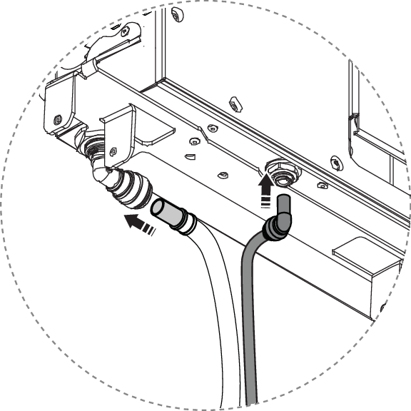
Apply fixture grease and connect the recirculation hose and flush hose to the Core.
It is important to relubricate the plug-in coupling and hose to prevent damage to the o-ring in the connection on the Core.
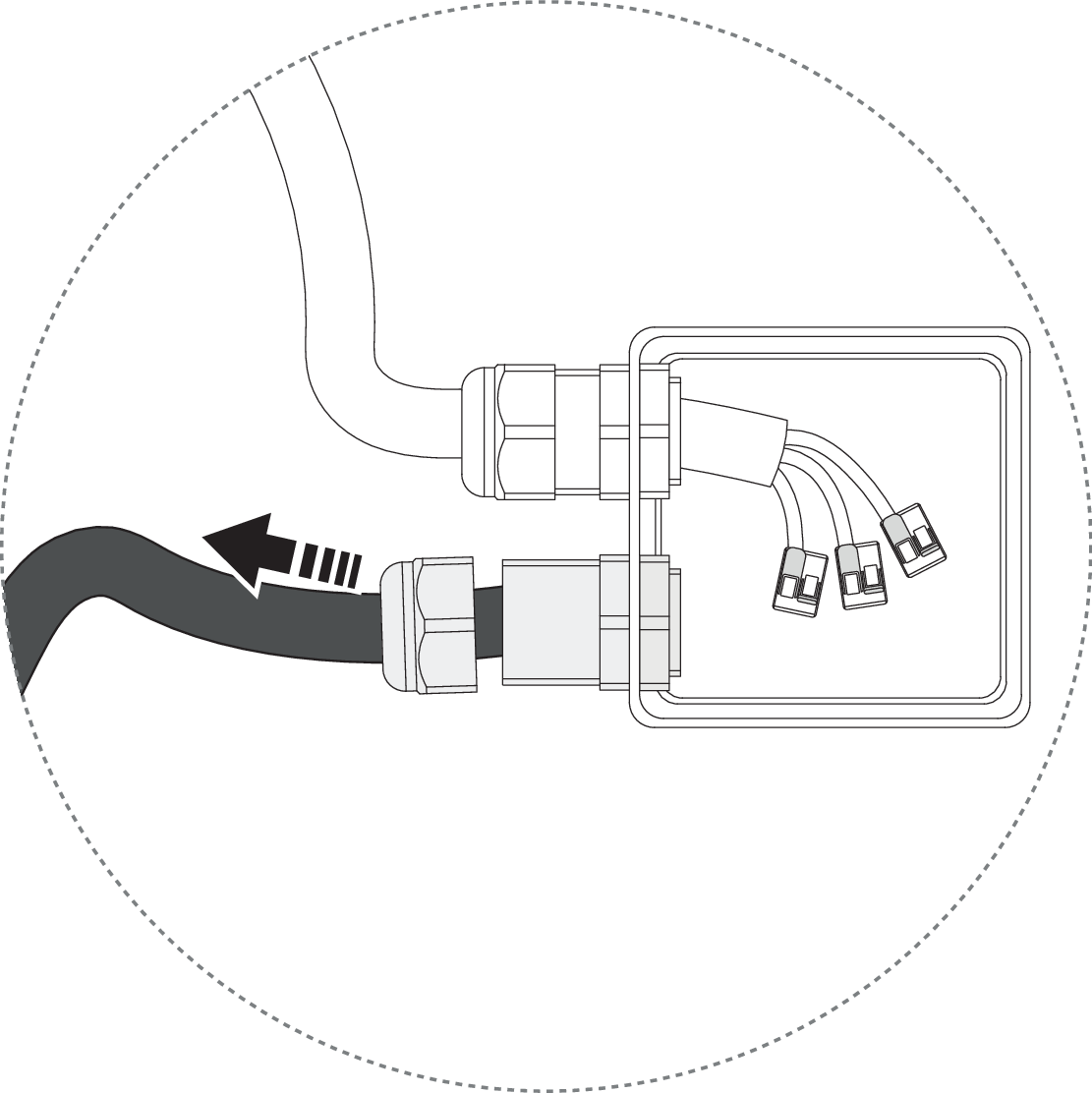
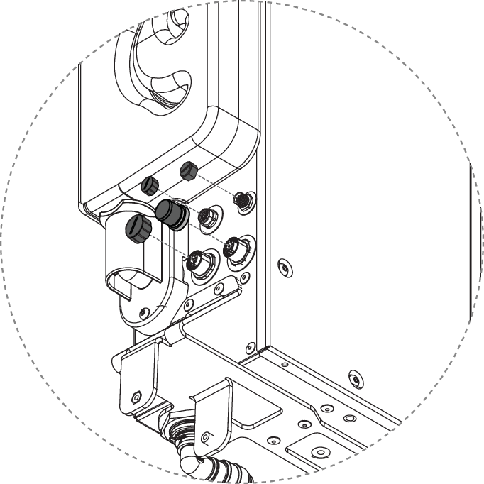
Unscrew the protective caps on the red and blue communication ports on the Core. Then plug in the Control Dial (red port) and Sensor Tank (blue port).
For installations with Audio: Unscrew the protective cap on the yellow communication port and plug in the amplifier. The contacts should be tightened by hand, and the cable to the Control Dial and amplifier should be routed behind the air gap tank.
Caution
Ensure a proper alignment between the connector and the communication port. This must be done with special attention to prevent damage to the pins.
Fit the protective caps on the old Core and place it in the packaging.
Turn on the incoming water. Check and fix any water leaks. Then turn on the power. It takes about 1 minute for Core to start up.
Replace the air gap tank cover.
Put the splash guards back in the Wall Box and close the door.
Verify the shower. Follow the guide here.
The replaced Core should be sent back to Orbital.
As per the instructions, make sure the plugs and protective caps are transferred from the new to the old Core.
Use the pallet, box, and foam inserts from the new Core to pack the old Core. Secure the box safely to the pallet using straps, tape, or similar.
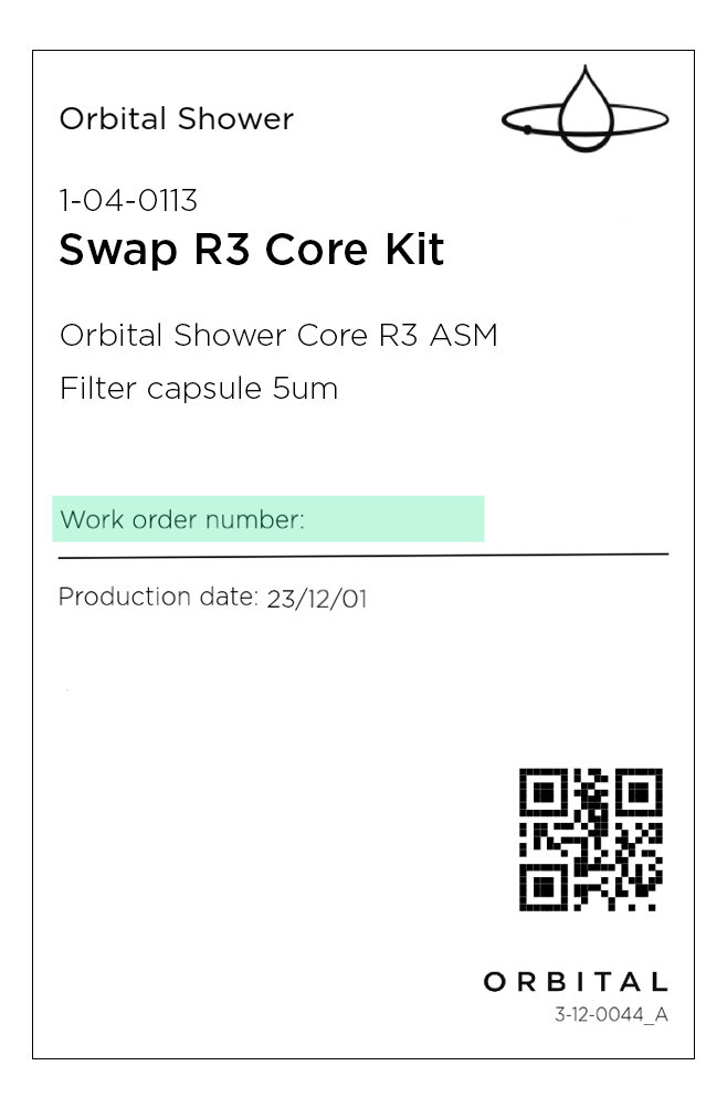
Record the work order number on the label if it is not already there, and contact Orbital to book the pickup.
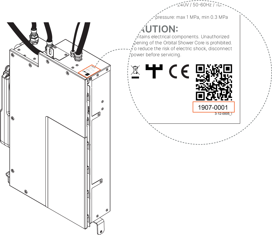
Complete and submit the service report (found in the service request). Please make sure to include the the new Core serial number, which is located on the top of the Core.
Recycle any other components.