2. Sensor Tank & Misc.
This instruction shows how to swap the Sensor Tank with accessories in a Hatch Tiled installation, where the Core is installed inside or outside of the shower area. Follow the instructions in detail, and don't hesitate to reach out if you have any questions - support@orbital-systems.com.
Use the following kit to swap the Sensor Tank.
Sensor Tank |
Sensor cable |
Flush hose |
Recirculation hose |
Tank accessory parts |
Dismantle Sensor Tank
Turn off the power.

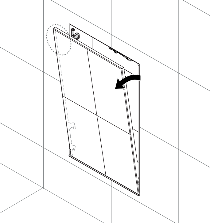
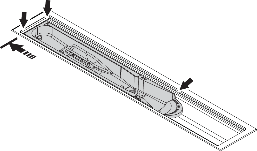
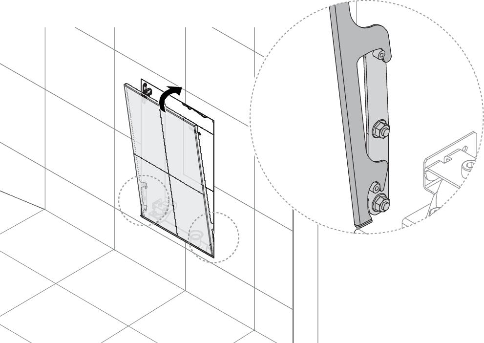
Push the top left corner to tilt the door open. Lift the door off the lower brackets. Be aware that the weight of the door is 8-12 kg, depending on the tile thickness.
Caution
The weight of the Hatch Tiled door is approximately 8-12 kg, depending on the tile thickness. Be careful when lifting.
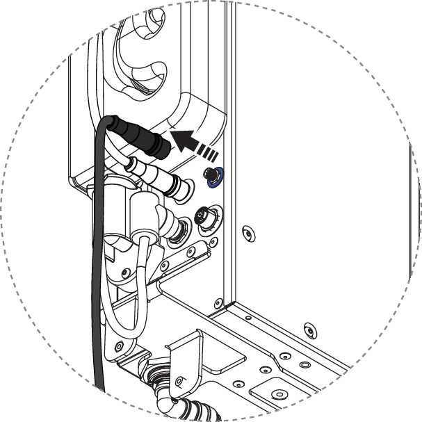
Disconnect the flush hose and recirculation hose from the bottom of the Core.

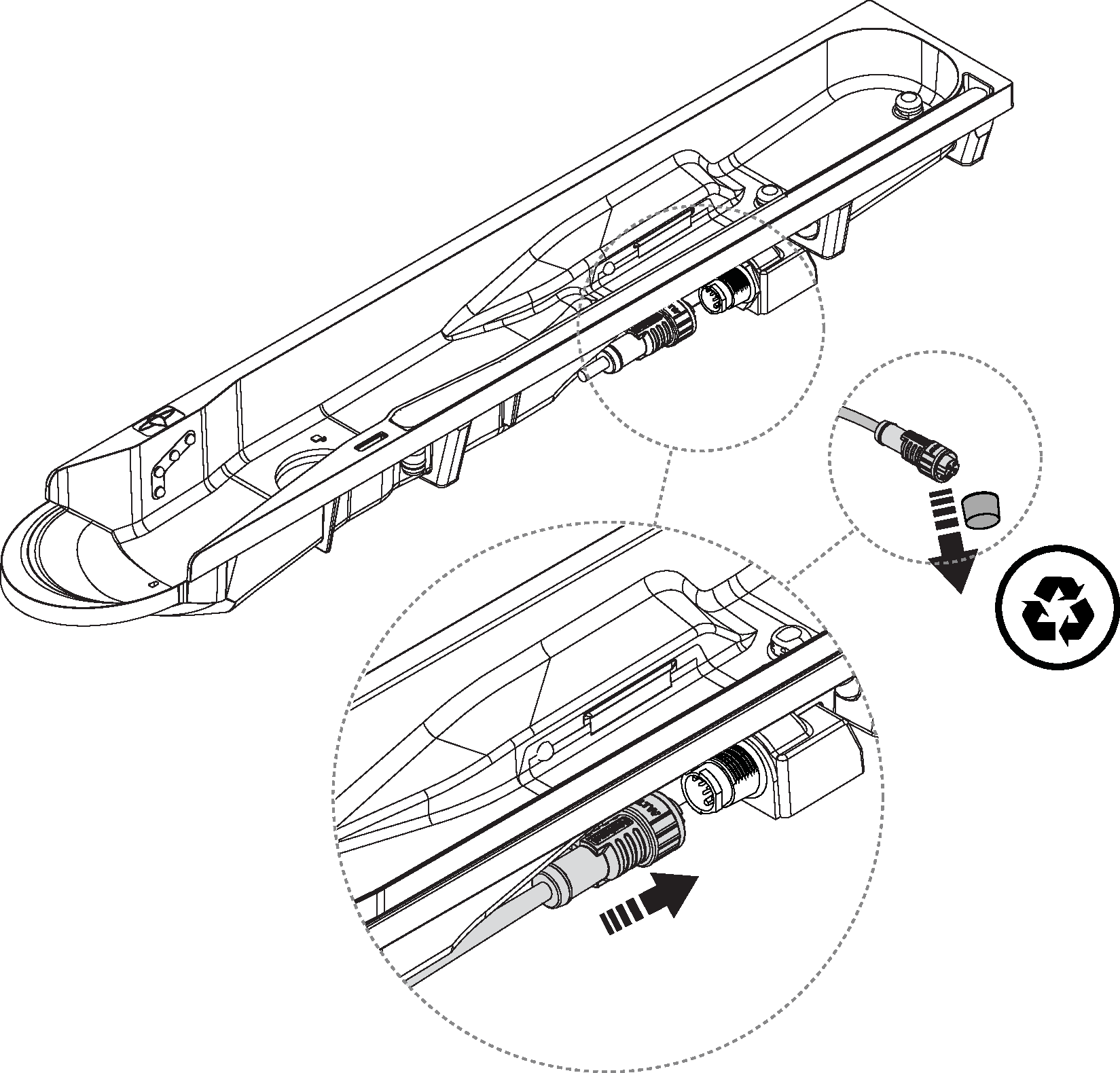
Disconnect the sensor cable.
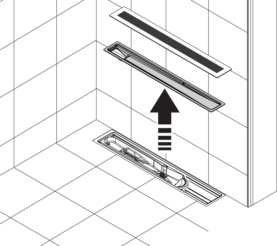
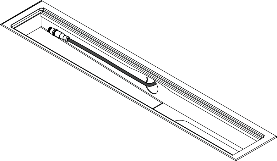
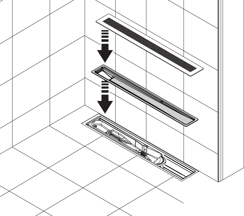
Lift the grate and Funnel.
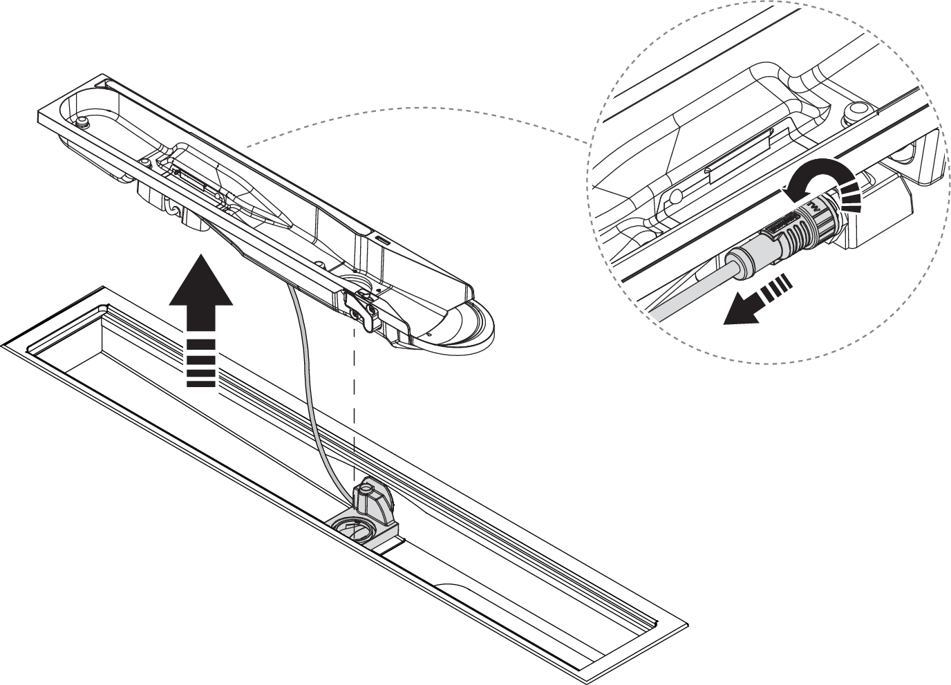
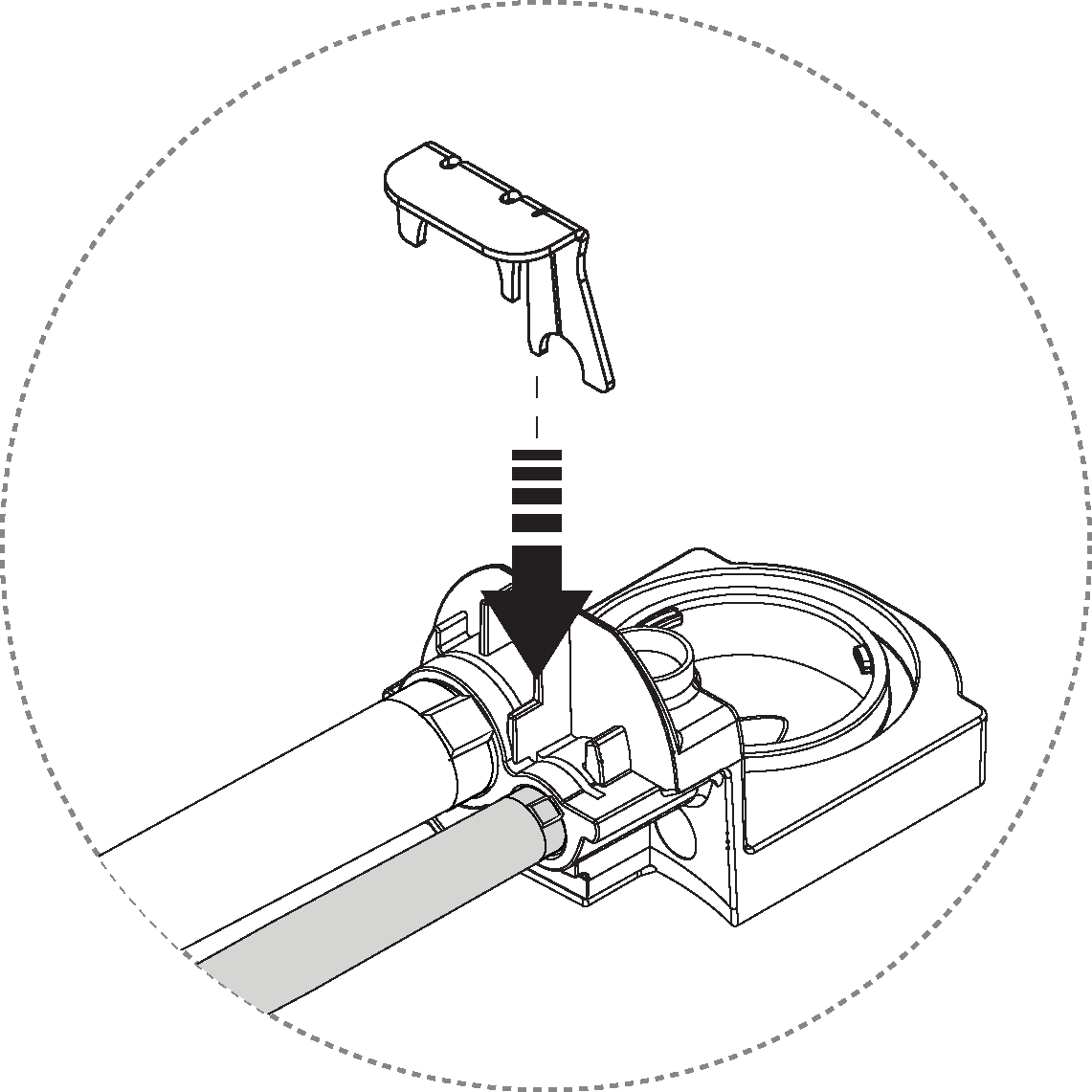
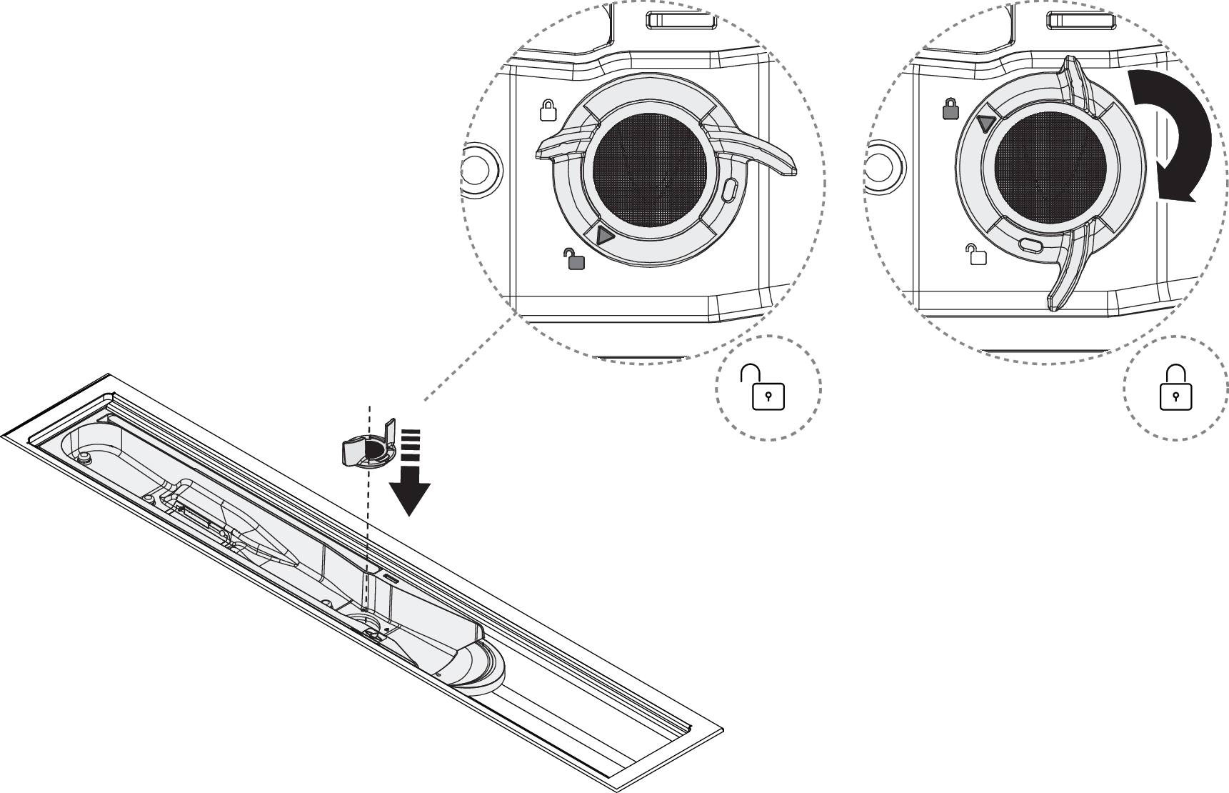
Unlock the Sensor Tank by turning the Sensor Tank Lock 90° counterclockwise.
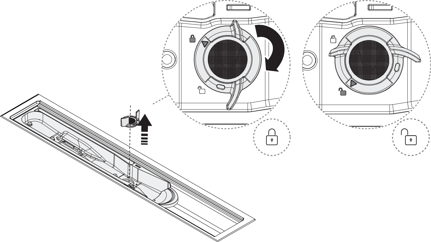
Lift the Sensor Tank and disconnect the sensor cable by unlocking the connector. Turn the connector flange 90° counterclockwise to unlock.
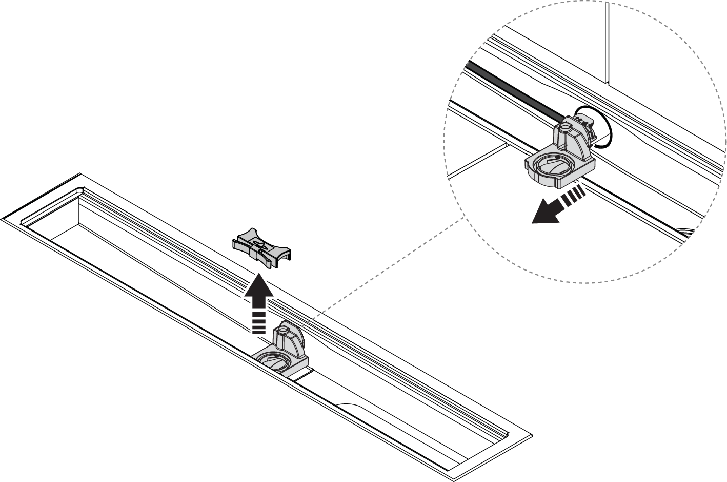
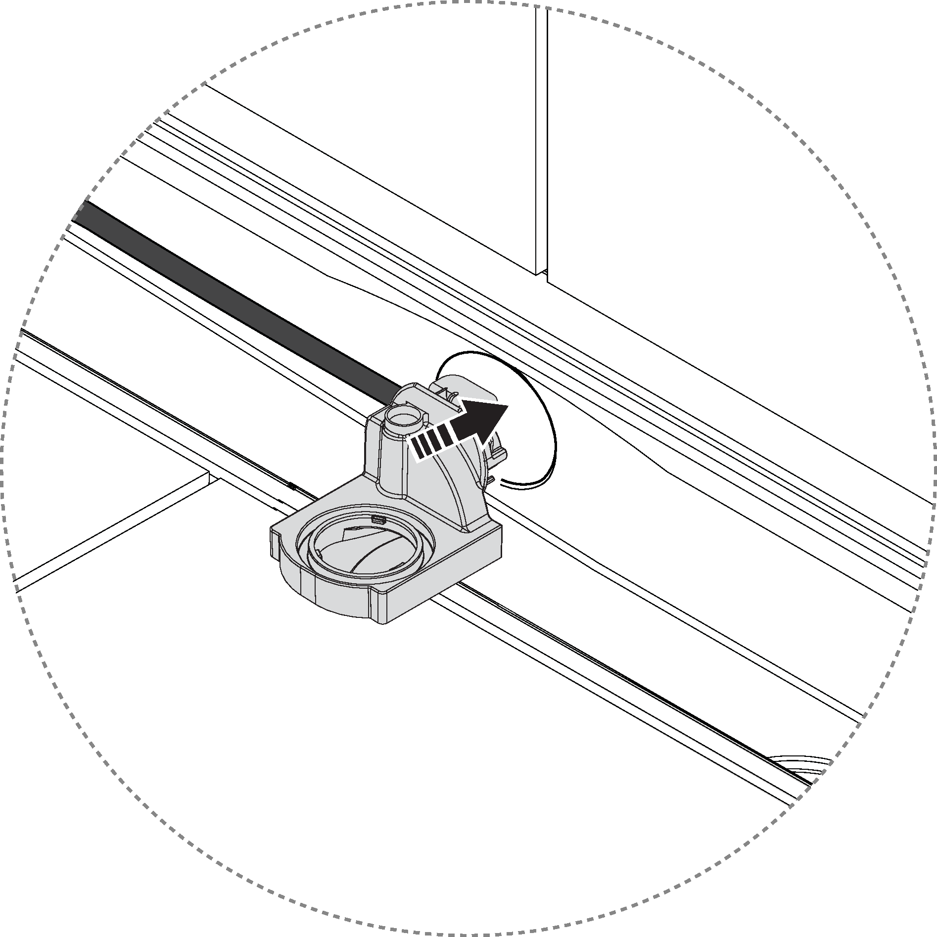
Remove the spring lock and pull out the Sensor Tank dock.
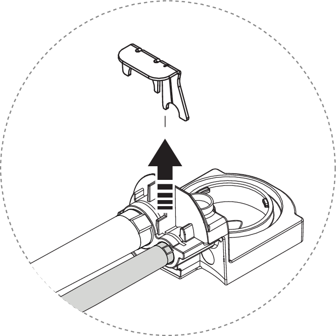
Remove the clip to release the hoses.
Release the Sensor Tank dock.
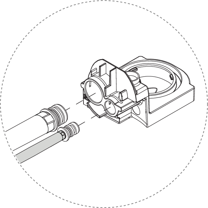
Pull out the flush hose.
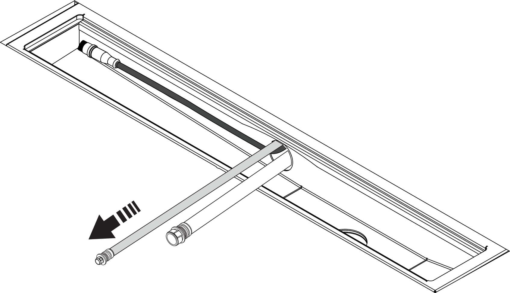
Pull out the recirculation hose.
Caution
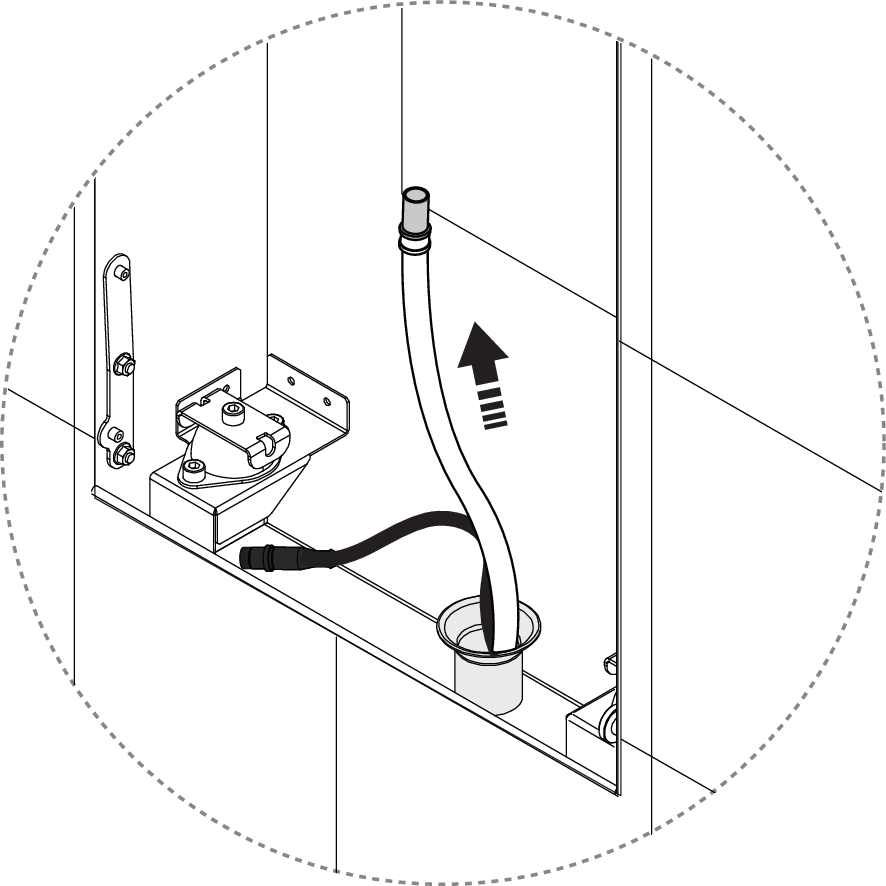
It is important that the circulation hose is pulled out from the top, to minimize the risk of the hose coupling getting stuck in the pipe.
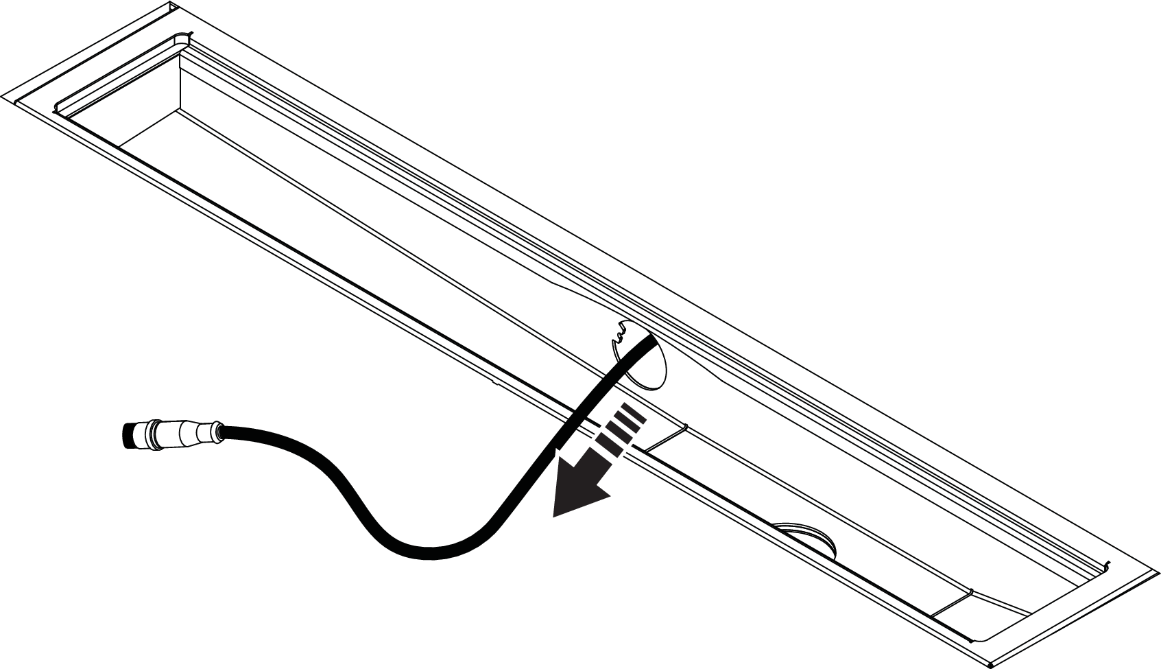
Pull out the sensor cable.
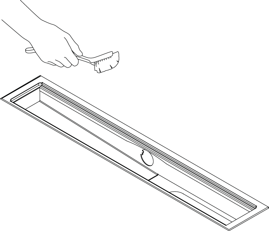
Install Sensor Tank
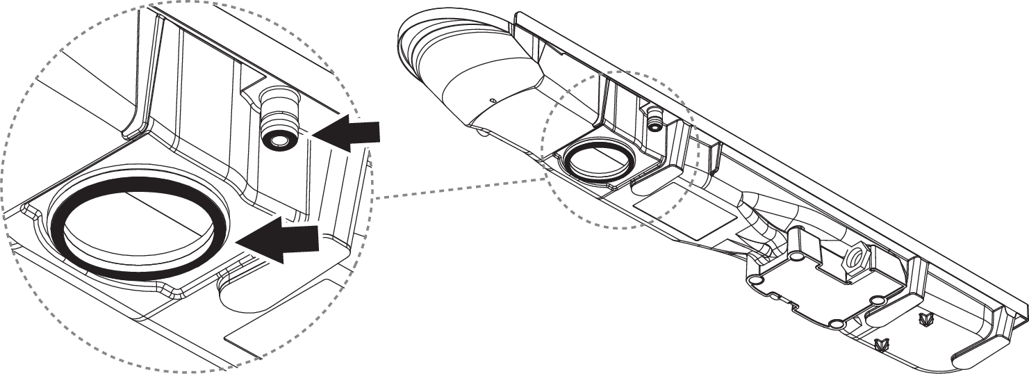
Clean the drain unit.
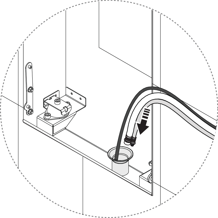
Route the sensor cable from the Wall Box through the connection pipe with the large connector down to the Sensor Tank. Pull out the cable to where it is about 150 mm left in the drain unit.
Tape the flush hose and the recirculation hose together at the end of the couplings, flush hose on the left. Make sure that the couplings, especially the o-rings, are carefully covered with tape.
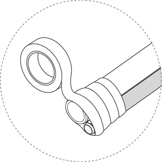
Pull the hoses through the connection pipe, with the couplings down towards the Sensor Tank. A tension spring is recommended for smooth installation.
Apply fitting grease and connect the hoses to the Sensor Tank dock.
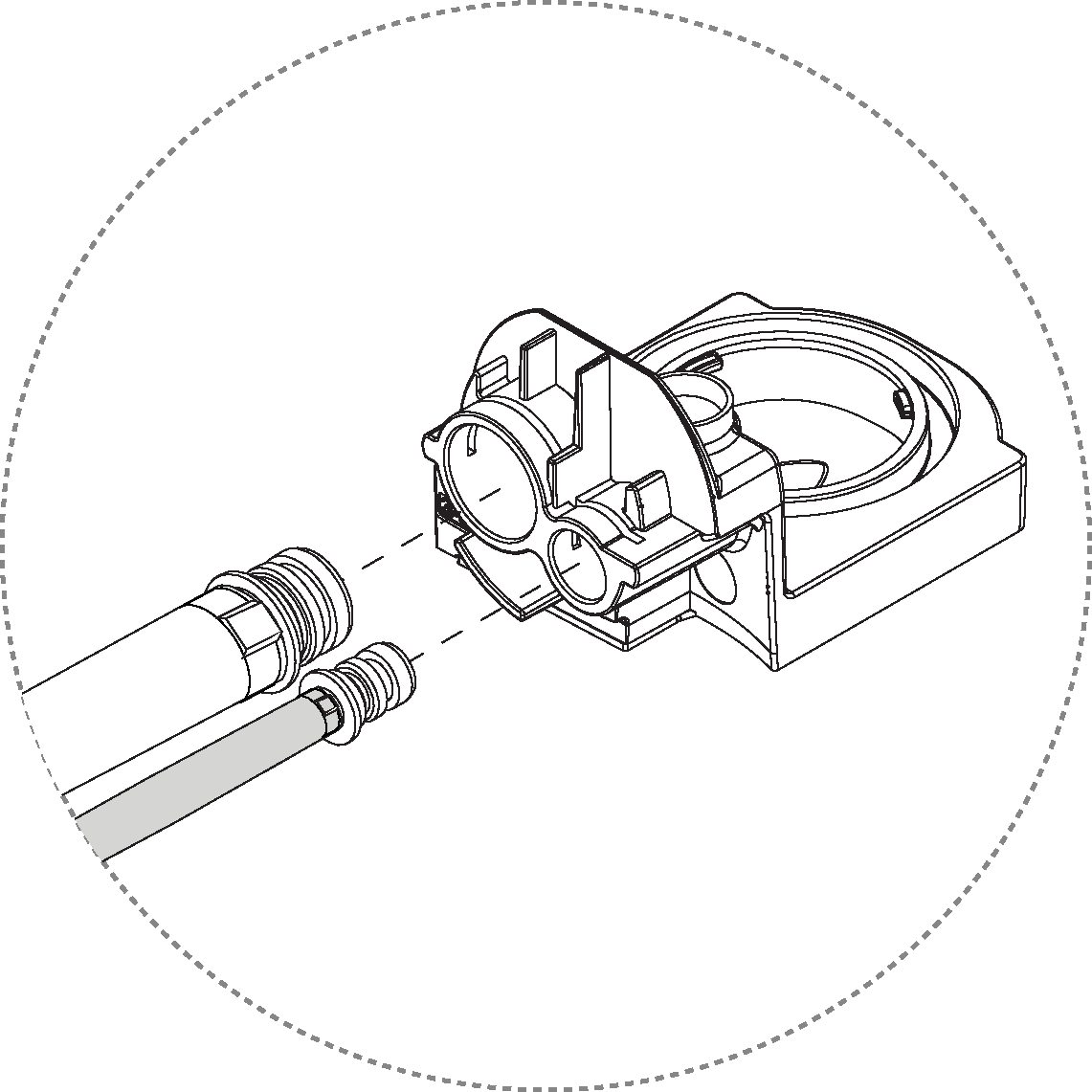
Lock the hoses using the clip. Press the clip down until it clicks.
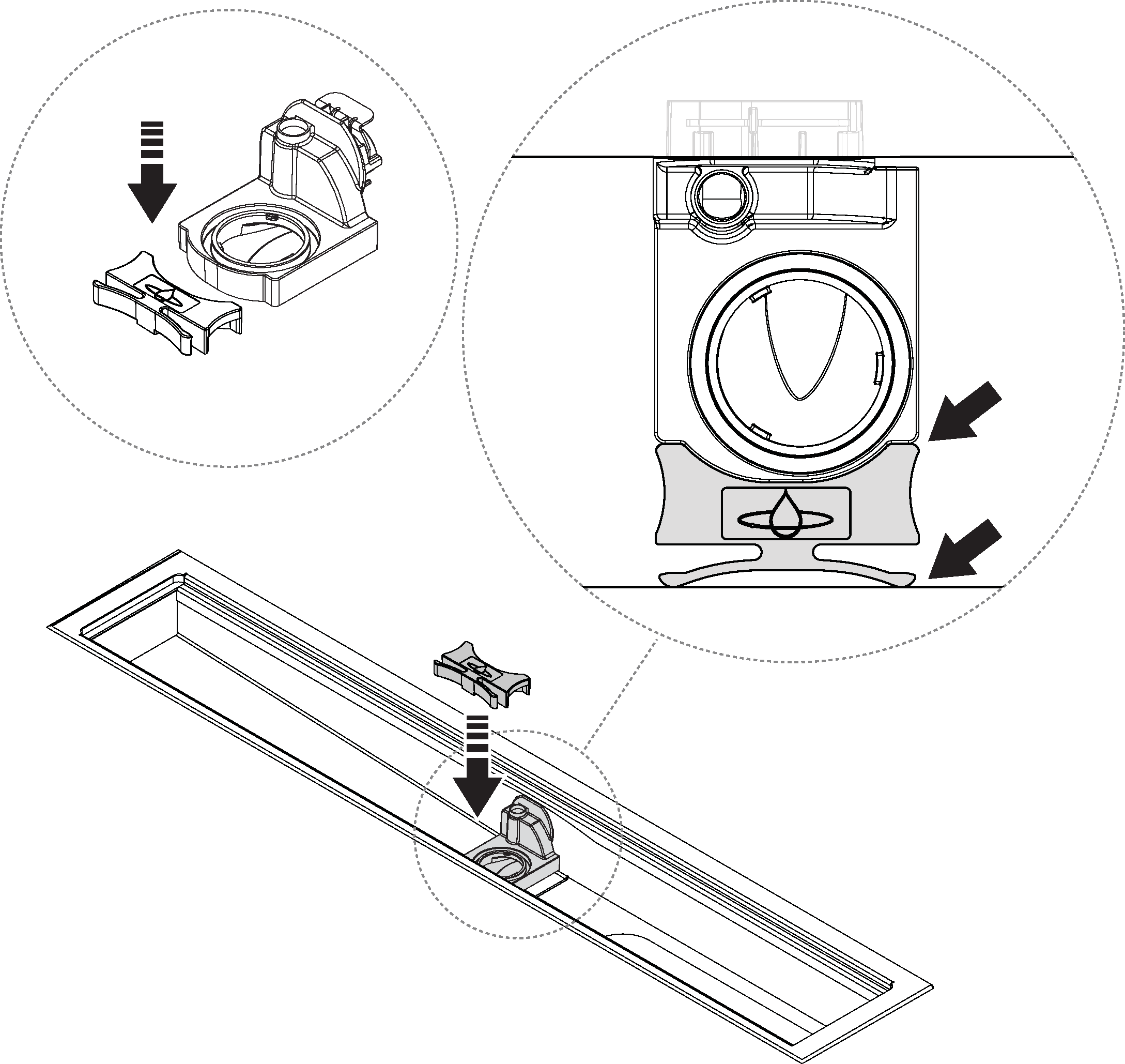
Insert the dock into the connecting pipe and push it all the way in.
Lock the Sensor Tank dock in place with the spring lock. Ensure that the sensor cable is not pinched.
Apply grease to the Sensor Tank o-rings.
Remove the protective cap from the sensor cable, and connect the cable to the Sensor Tank.
Caution
Make sure to have correct alignment between the groove and the pin when connecting.
Insert the Sensor Tank to the drain unit.
Caution
Make sure the Sensor Tank is inserted correctly. Its edge should be fully pushed towards and at level with the edge of the drain unit.
Lock the Sensor Tank in place by turning the Sensor Tank Lock 90° clockwise.
Place the Funnel and grate back in place.
Note
Place the Funnel with the hole oriented to the left! Placing the hole oriented to the right will disable recirculation.
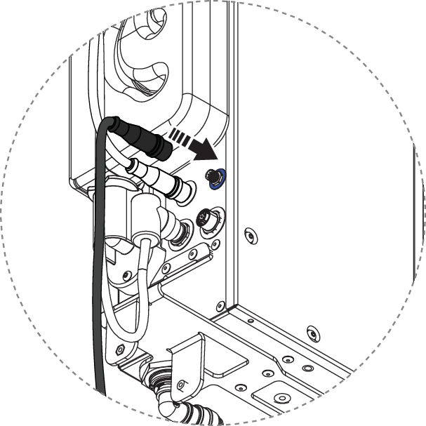
Connect the sensor cable to the communication port on the Core (blue port). The connector should be tightened by hand.
Caution
Ensure correct alignment between the connector and communication port. This must be done with particular attention to prevent damage to the pins.
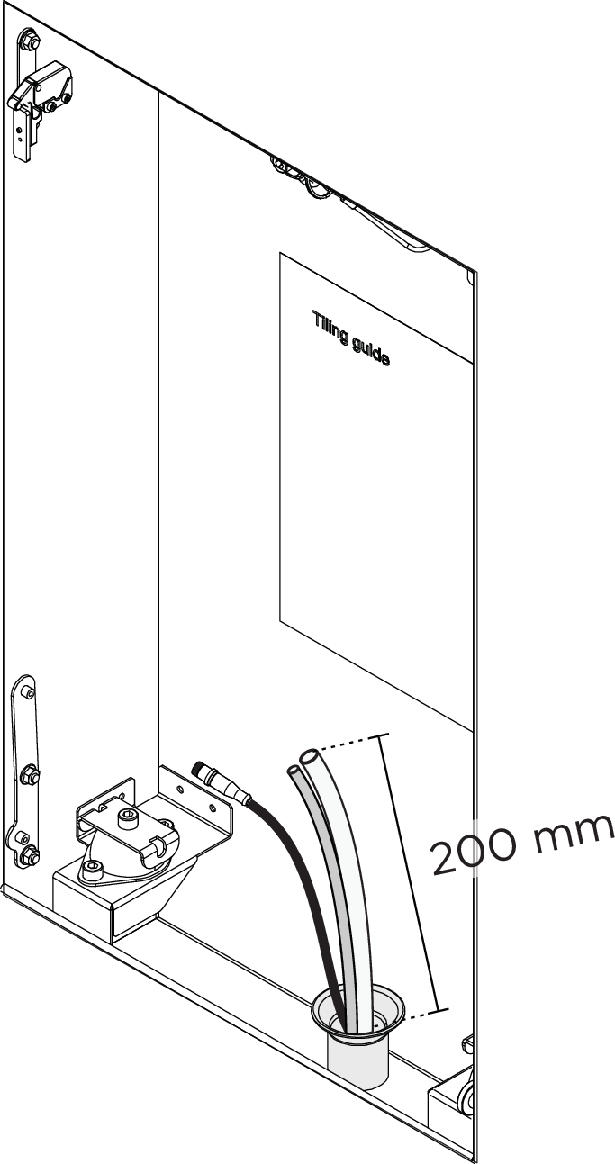
Cut the circulation hose and the flushing hose according to the measurements below from the rubber grommet of the Wall Box, or from the connection pipe in the case of an installation with Basic, depending on the installation.
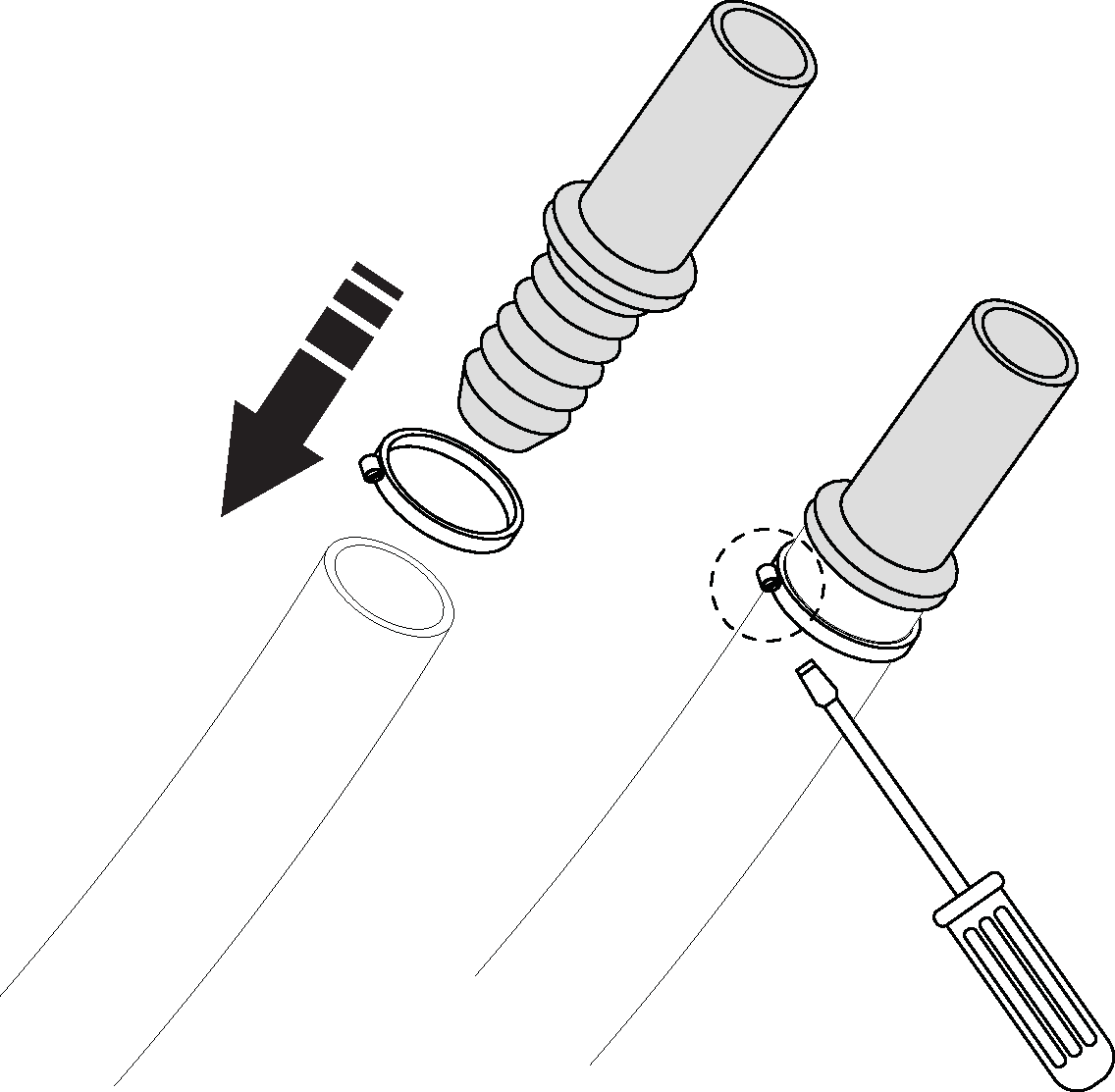
Apply fitting grease to the separate hose coupling, push all the way into the circulation hose and tighten with the hose clamp.
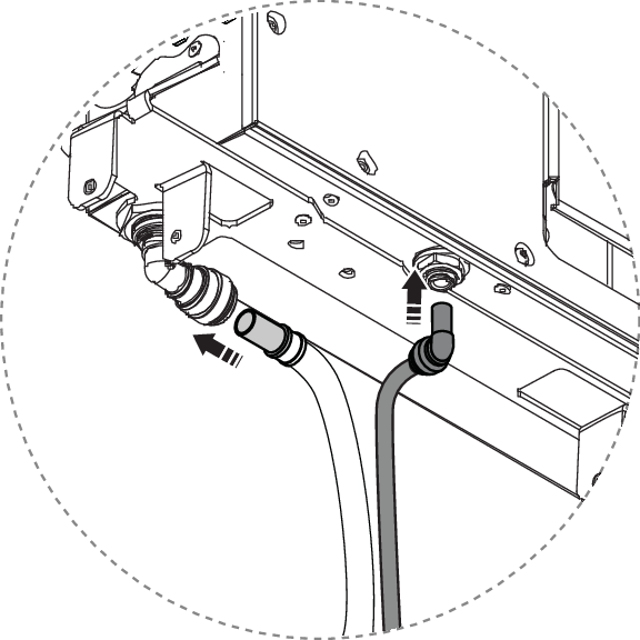
Apply fixture grease and connect the recirculation hose and flush hose to the Core.
Secure the door onto the brackets, tilt it inward to close it, and press the upper left corner to lock it in place.
Turn on the power.
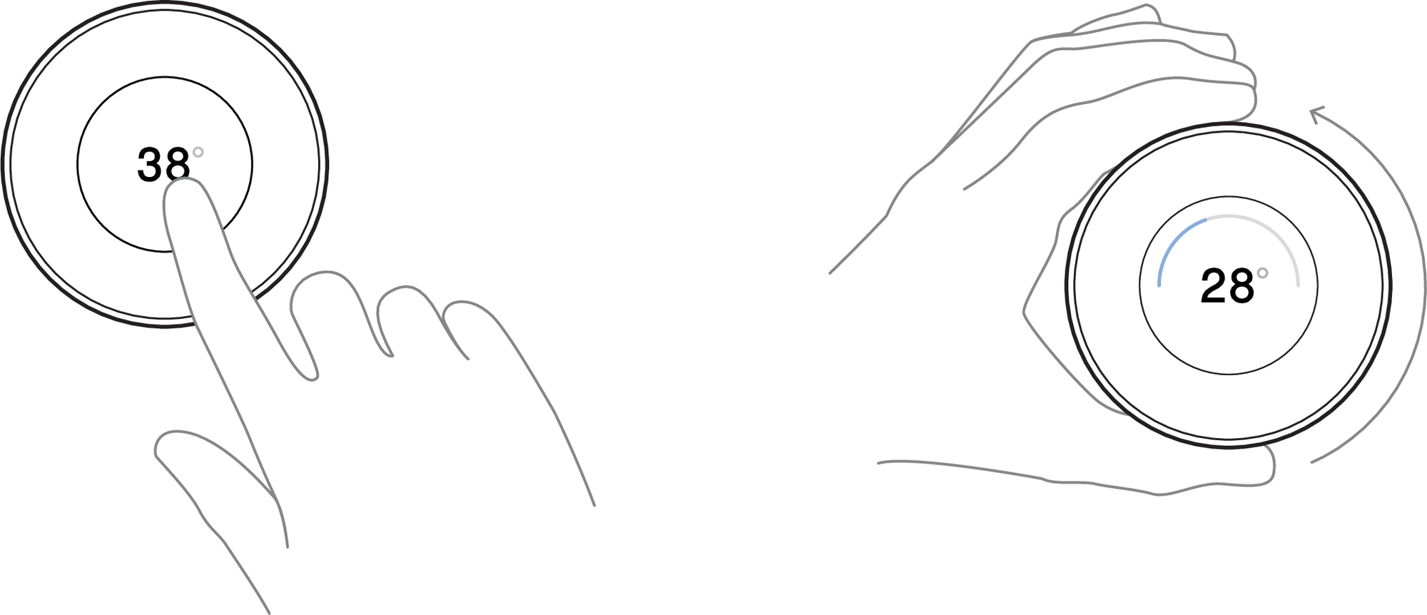
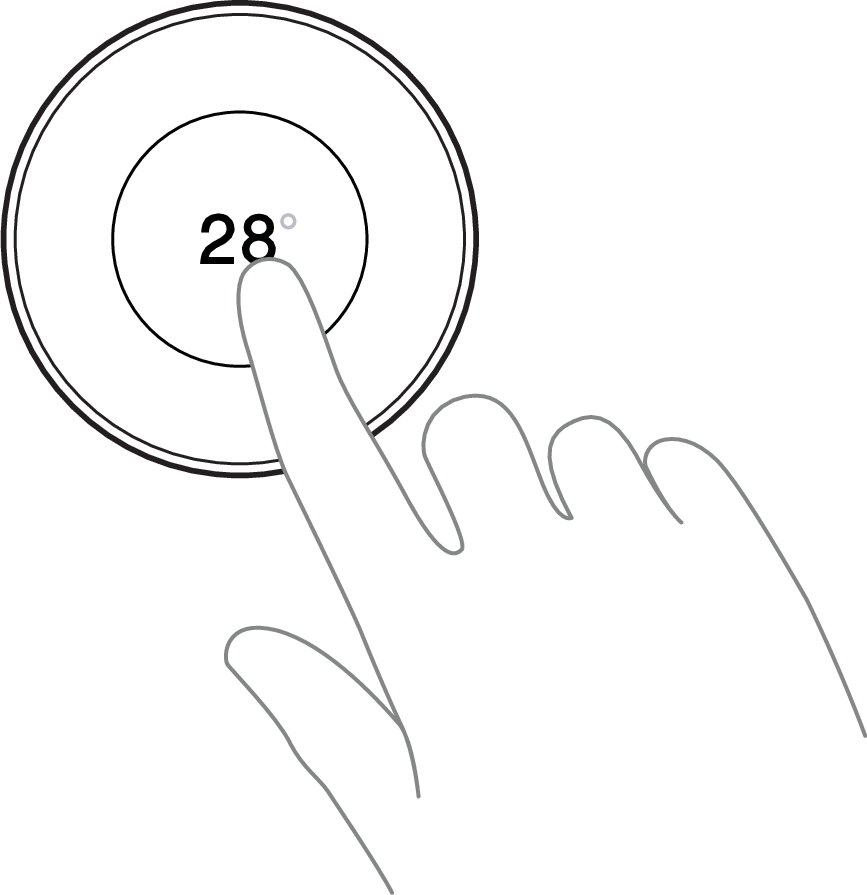
Start the shower to validate the Sensor Tank replacement. Set the temperature to 28°C. The shower should start recycling and show a count on the Control Dial within 5 minutes without increased noise level.
Turn off the shower.
Complete and submit the service report (found in the service request).
Recycle the parts and components that should not be reused.