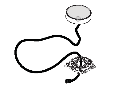
Install Control Dial
 |
Notice
Do not remove the protective cover from the Control Dial until the installation is completed.
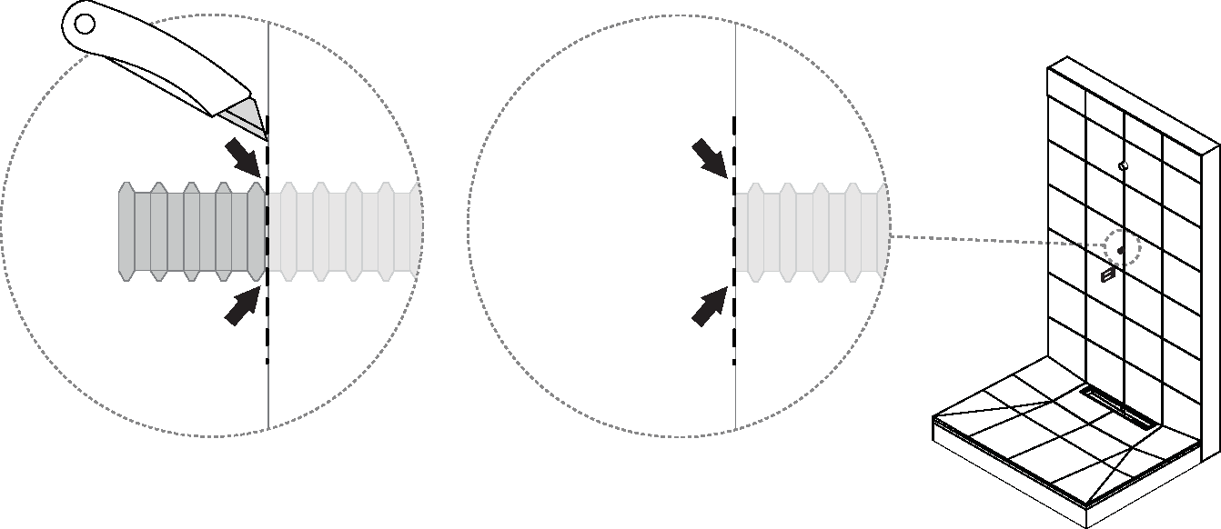
Cut the conduit flush to the tile surface.
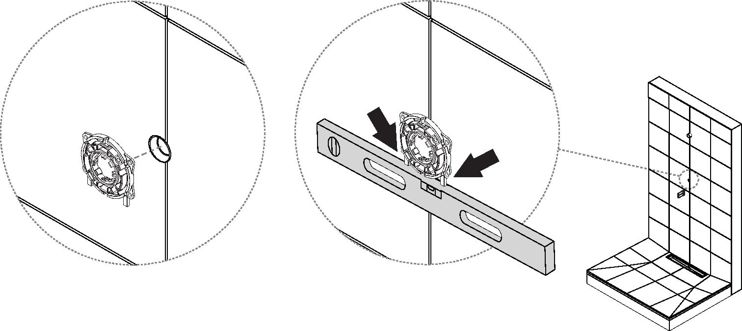
Level the fixture and make sure it is centred on the hole in the wall. Measure and mark the outer holes.
Drill 4 holes in the marked locations, and mount the bracket with the screws supplied.
Caution
Only drill through the tile itself, no deeper.
Seal drill holes according to industry rules. See section Seal mountings in wet zone for instruction.
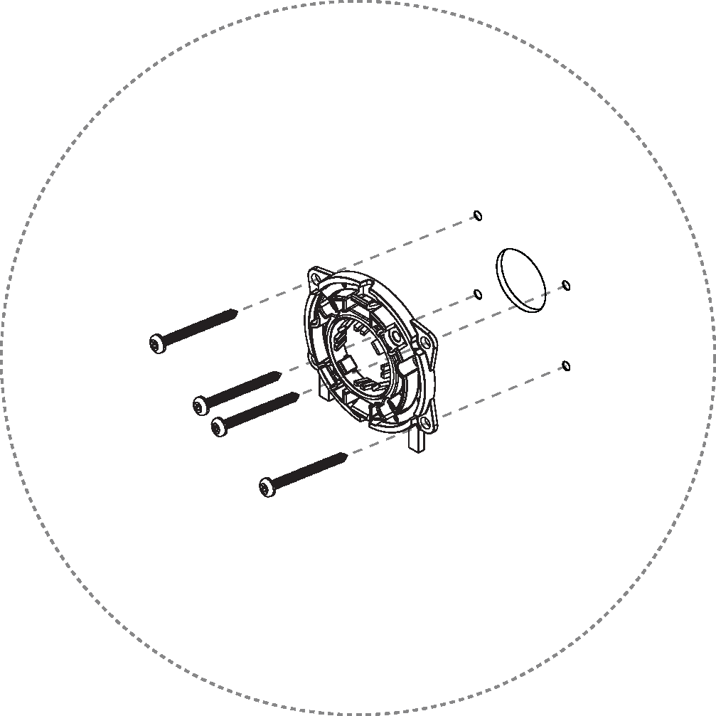
x4
TX screw A4 (38 mm)
Connect the Control Dial cable to the extension cord.
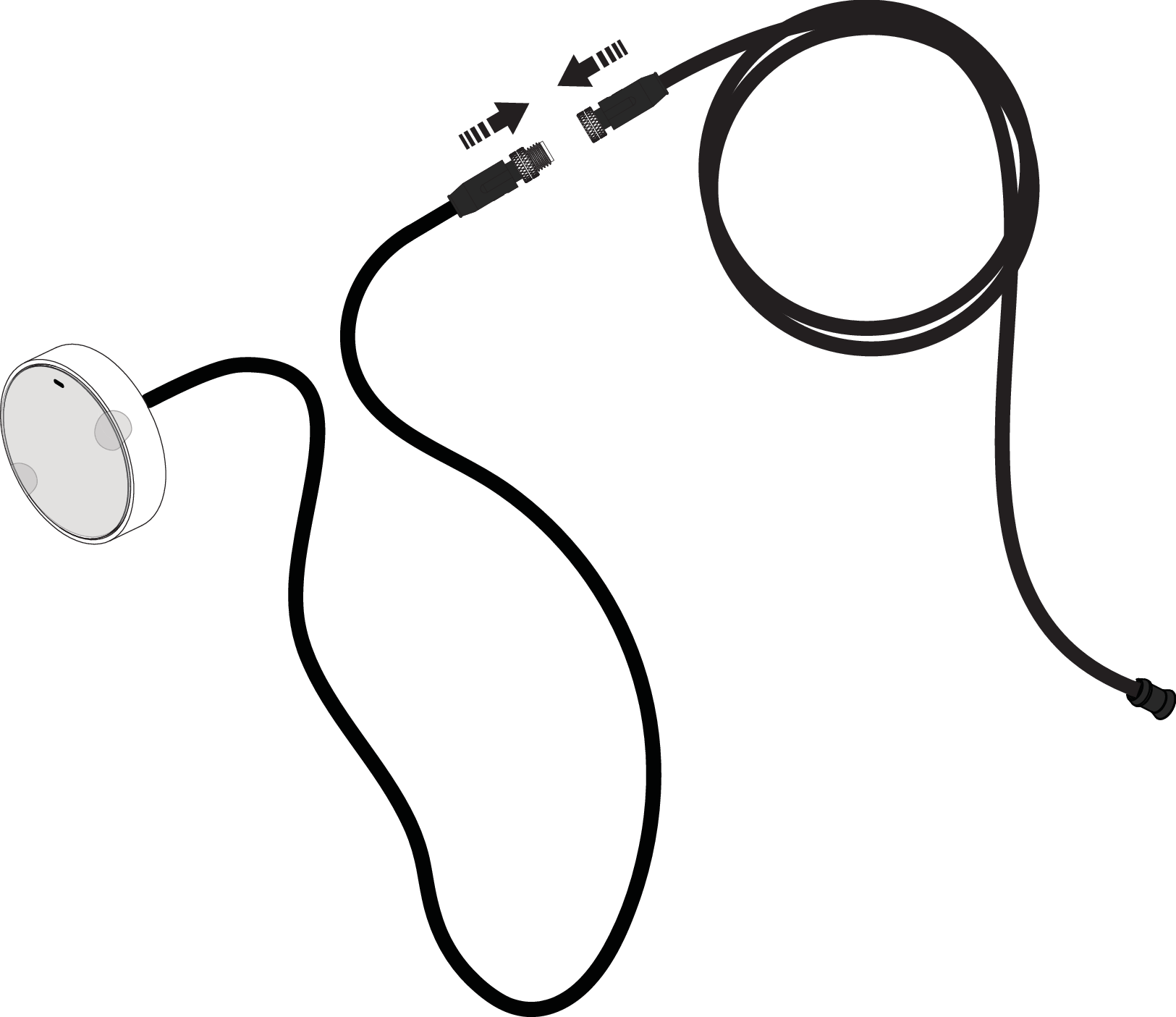
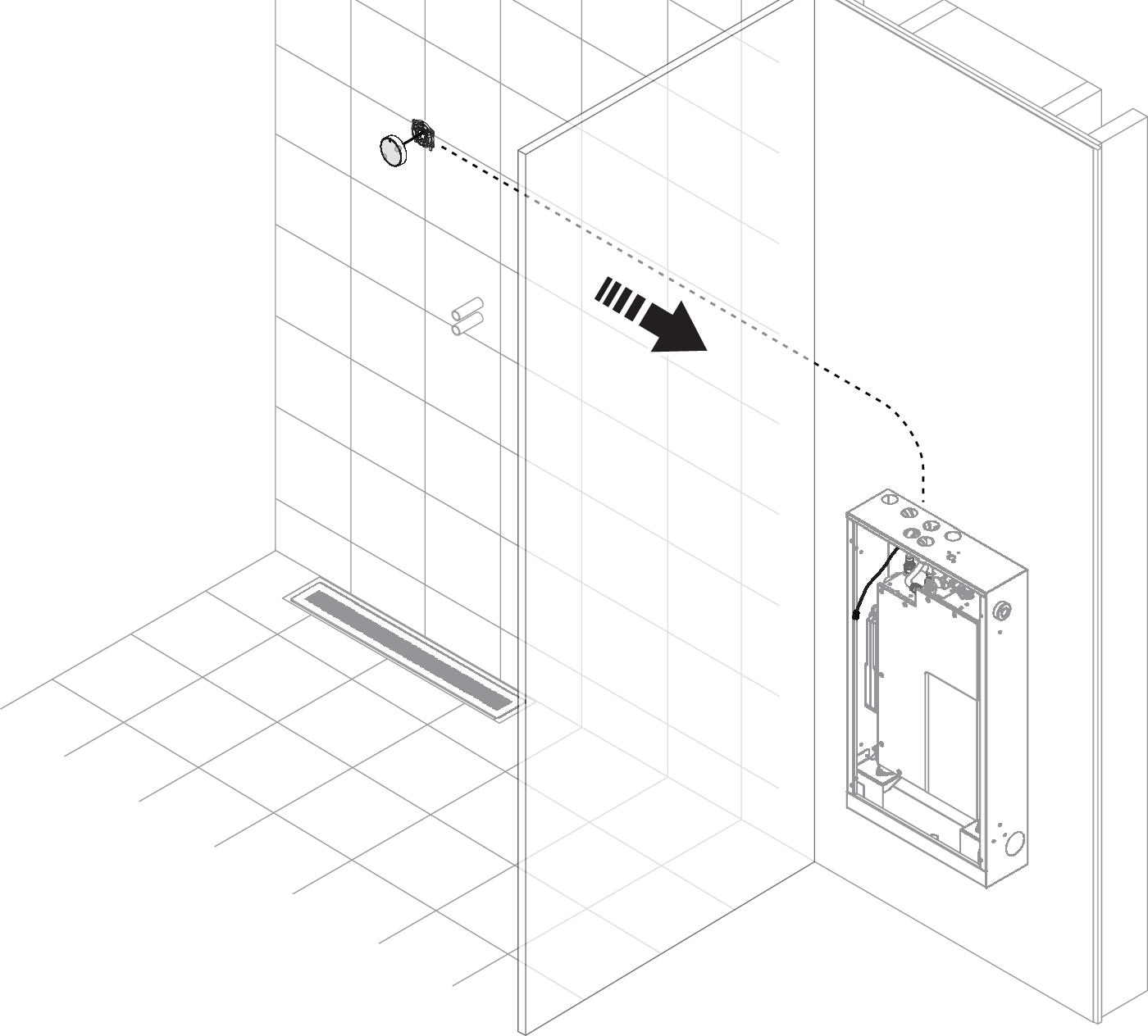
Pull the cable through the conduit.
Notice
It is recommended to use fish tape to route the cables through the pipes.
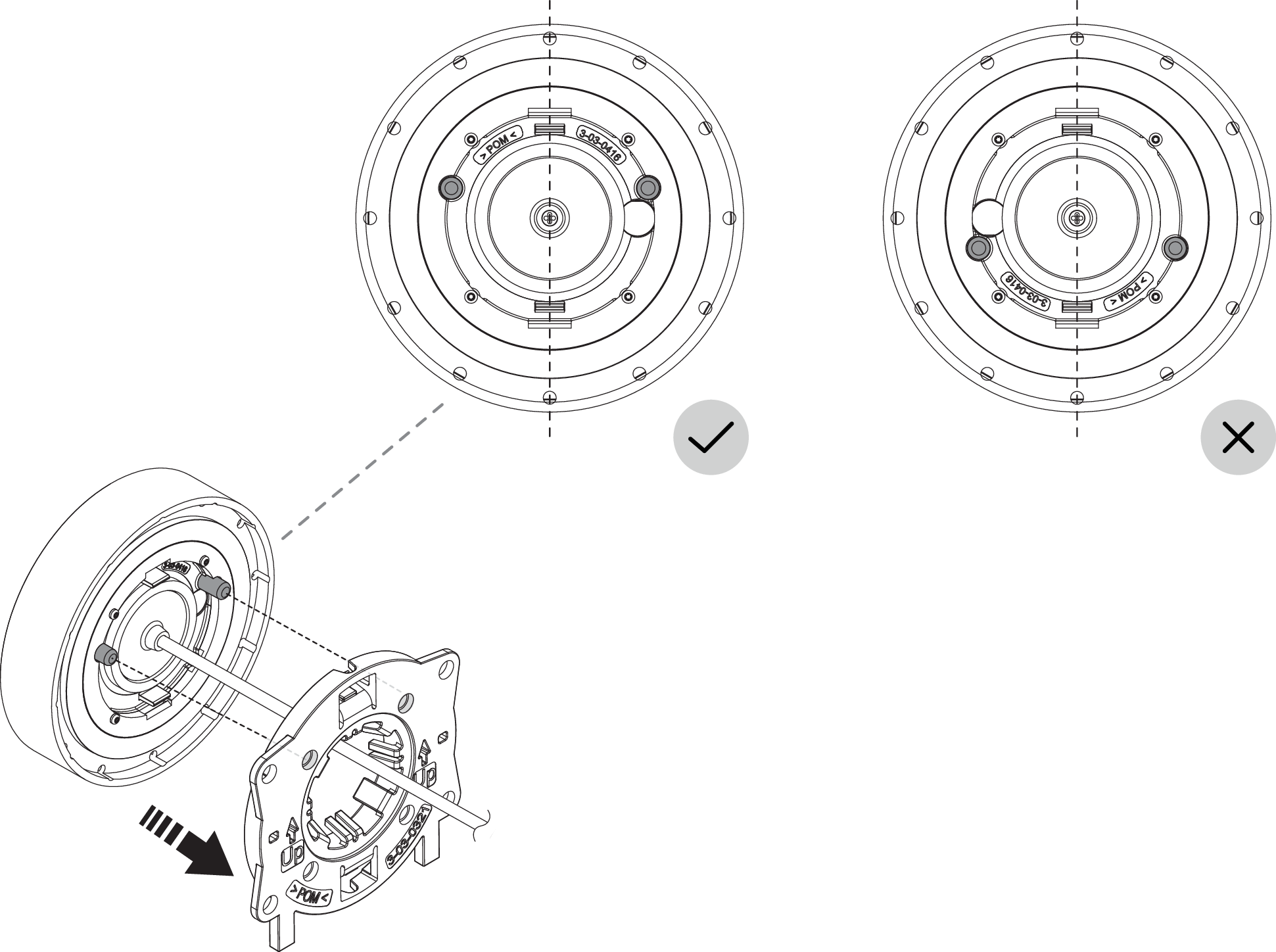
Position the Control Dial according to the “up marking” before assembly. Snap the Control Dial onto the fixture, and make sure to align the brackets according to the arrows.
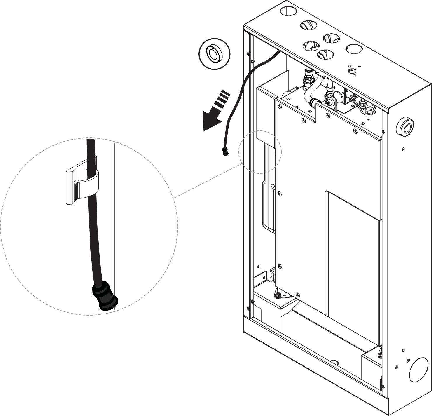
Attach the cable to the cable channel in the Wall Box.
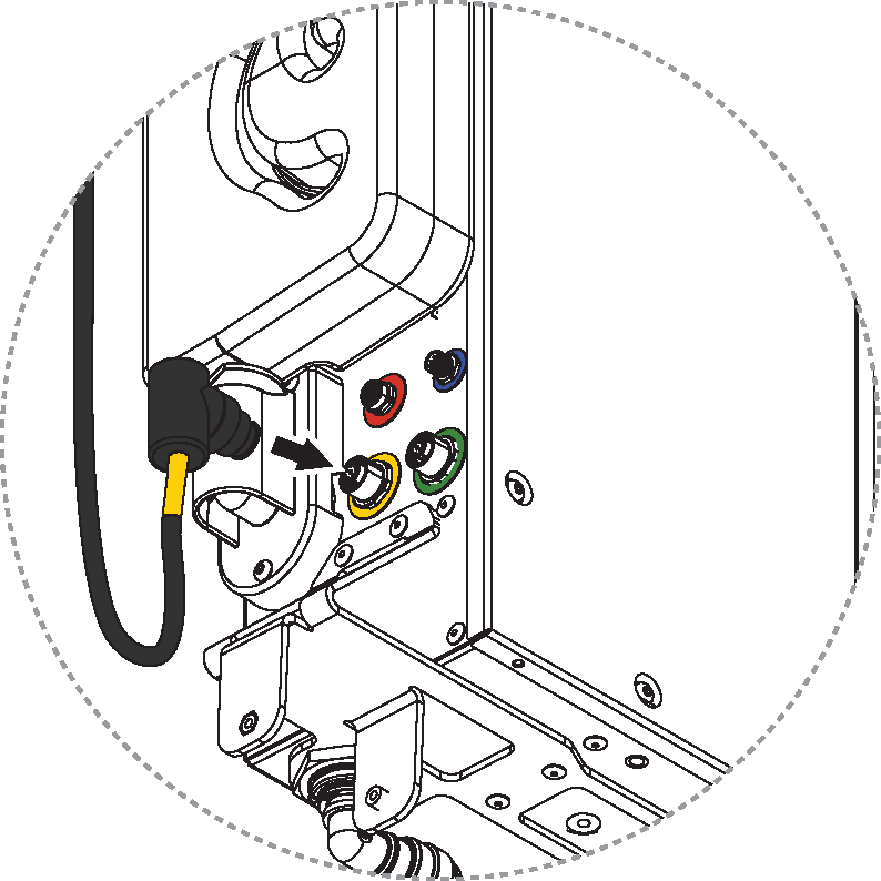
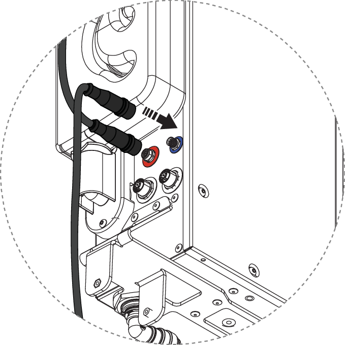
Connect the Control Dial cable to the red connector. Proceed by connecting the Sensor Tank cable to the blue connector.
Caution
Make sure to have correct alignment between key and slot in connectors. This must be done with attention to prevent damage to the pins. Make sure locking ring snaps and connector is locked.
Only valid for Orbital Audio Installation
Connect the amplifier cable to the yellow connector.
